
Reducing layer-2 protocol overhead by improving layer processing efficiency

a layer-2 protocol and layer processing technology, applied in the field of transmission and reception processing, can solve the problems of requiring even lower delays, data delivery cannot be guaranteed, transmission window cannot be advanced, etc., and achieve the effect of reducing layer-2 protocol overhead, increasing header overhead, and increasing header overhead

Active Publication Date: 2021-08-17
PANASONIC INTELLECTUAL PROPERTY CORP OF AMERICA
View PDF13 Cites 0 Cited by
  • Summary
  • Abstract
  • Description
  • Claims
  • Application Information

AI Technical Summary

Benefits of technology

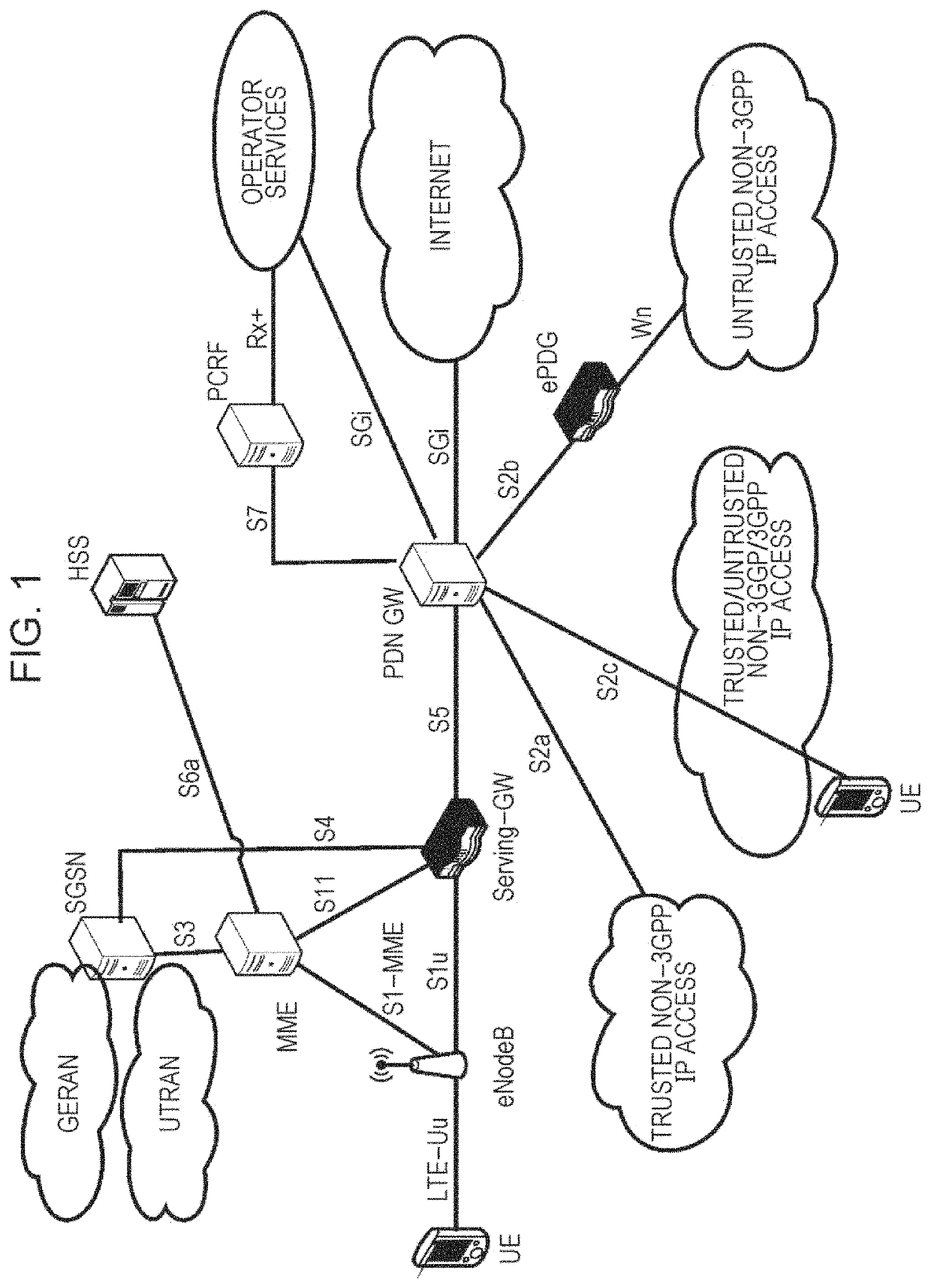
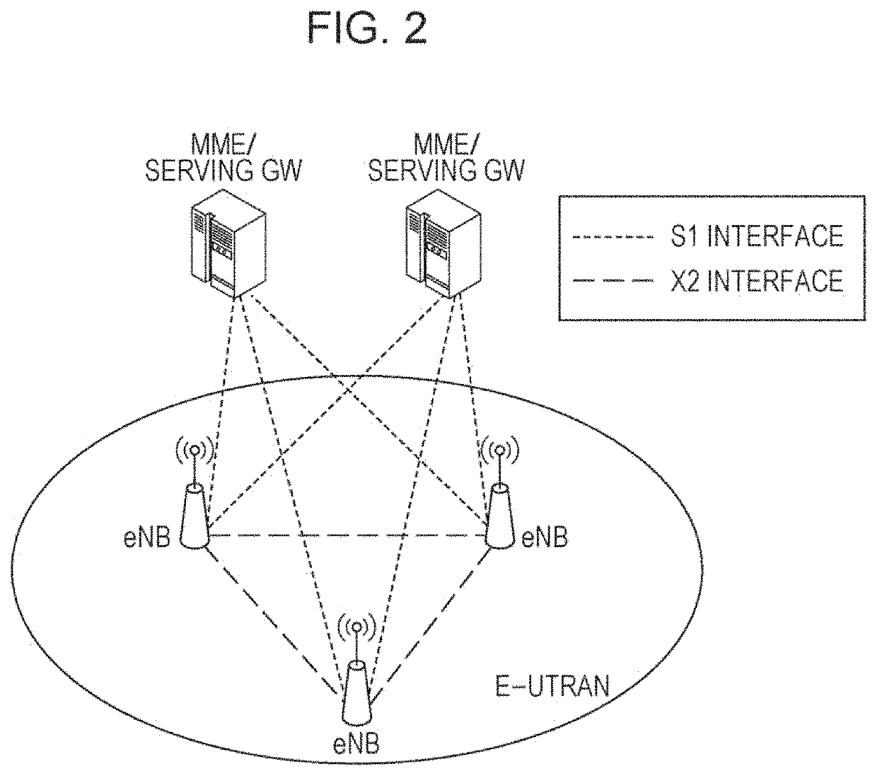
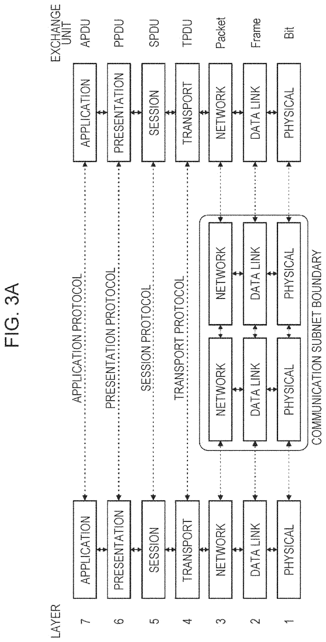
The U-Plane protocol architecture aims to reduce the layer-2 protocol overhead in LTE networks. The design goal is to minimize the number of fields that increase header overhead, such as the Length field and the sequence numbers used by PDCP and RLC. This approach improves the efficiency of layer processing and reduces the impact on network performance.

Problems solved by technology

Furthermore, it may detect and correct potential transmission errors by requesting a retransmission of a lost frame.
One of the main challenges for the LTE link-layer design is to provide the required reliability levels and delays for Internet Protocol (IP) data flows with their wide range of different services and data rates.
Consequently, downloads at very high data rates (e.g., 100 Mb / s) require even lower delays and, in addition, are more sensitive to IP packet losses than VoIP traffic.
In Unacknowledged Mode data delivery is not guaranteed since no retransmission protocol is used.
Therefore, if the RLC status report is delayed, the transmission window cannot be advanced and the transmission might get stuck.
Although the absolute priority-based method is quite simple in terms of UE implementation, it sometimes leads to starvation of data from low-priority logical channels.
Starvation means that the data from the low-priority logical channels cannot be transmitted because the data from high-priority logical channels take up all the MAC PDU space.
The reason for introducing the logical channel group concept is that even though the UE may have more than four logical channels configured, reporting the buffer status for each individual logical channel would cause too much signaling overhead.
As NR is targeting for very high data rates, the processing time available for both transmitter and receiver might be very limited compared with the amount of data to be transmitted.
However RLC and MAC PDUs can only be generated in real-time manner (i.e. after reception of the UL grant).
The inability to perform “pre-processing” incurs a processing delay upon grant reception.
Additionally, PDCP and RLC use their own sequence numbers in the existing LTE protocol architecture, which also increases header overhead.

Method used


Image

  • Reducing layer-2 protocol overhead by improving layer processing efficiency
  • Reducing layer-2 protocol overhead by improving layer processing efficiency
  • Reducing layer-2 protocol overhead by improving layer processing efficiency

Examples


Embodiment Construction

Basis of the Present Disclosure

L1 / L2 Processing

[0100]FIG. 4 exemplary depicts the data flow of an IP packet through the link-layer protocols down to the physical layer. The figure shows that each protocol sublayer adds its own protocol header to the data units as well as the mapping of the transport block on a subframe. Transport block (TB) denotes the MAC PDU which is mapped onto the physical layer.

[0101]The mapping of the transport block onto the subframe in LTE is performed within a so-called transmission time interval (TTI). Generally a single transport block is mapped in one TTI to one subframe in case of single input single output (SW), i.e. transmitter and receiver operating with one antenna. In case of MIMO / MISO (multiple input multiple output / multiple input single output), two codewords corresponding to two transport blocks may be mapped in one TTI to the physical resources. In general, more than two transport blocks may be considered for mapping.

[0102]The LTE L2 functions ...


PUM


Abstract

The layer processing includes at least processing on a first, a second and a third layer. At the transmitter side, the third layer receives a packet, adds its header and forwards the packet to the second layer. The second layer performs segmentation and provides segmented data to the first layer, which maps the segmented data onto physical resources. The segmentation is based on the allocated resources. Retransmissions may take place on the third layer and thus, the third layer may re-segment the packet according to the received feedback for particular segments and provide the re-segmented data to the lower layers. Alternatively, the feedback information is provided to the second layer which then performs the segmentation by taking it into account. Correspondingly, the receiver performs re-ordering and re-assembly at the third layer for which it receives also control information from the second layer.

Description

BACKGROUND1. Technical Field[0001]The present disclosure relates to transmission and reception processing on multiple layers in a communication system as well as to the corresponding transmission apparatuses, methods and programs.2. Description of the Related Art[0002]Third-generation mobile systems (3G) based on WCDMA radio-access technology are being deployed on a broad scale all around the world. A first step in enhancing or evolving this technology entails introducing High-Speed Downlink Packet Access (HSDPA) and an enhanced uplink, also referred to as High Speed Uplink Packet Access (HSUPA), giving a radio-access technology that is highly competitive. In order to be prepared for further increasing user demands and to be competitive against new radio access technologies, 3GPP introduced a new mobile communication system called Long Term Evolution (LTE). LTE is designed to meet the carrier needs for high speed data and media transport as well as high capacity voice support throug...

Claims


Application Information

Patent Timeline
Patent Type & Authority Patents(United States)
IPC IPC(8): H04W80/02H04L1/16H04W76/15H04L1/18H04W28/06H04W80/08H04L1/00
CPCH04W80/02H04L1/1642H04L1/1671H04L1/1861H04W28/065H04W76/15H04W80/08H04L1/0007H04L1/1685
Inventor SHAH, RIKINLOEHR, JOACHIMBASU MALLICK, PRATEEKHORI, TAKAKO
Owner PANASONIC INTELLECTUAL PROPERTY CORP OF AMERICA
Learn More