Suction regulator and fluid drainage system

a technology of fluid drainage system and pressure regulator, which is applied in the direction of suction drainage containers, valve operating means/releasing devices, functional valve types, etc., to achieve the effect of accurate and efficient way of selective pressure regulation and accurate and efficient way

Inactive Publication Date: 2005-10-18
DANTONIO CONSULTANTS INT INC
View PDF25 Cites 23 Cited by
  • Summary
  • Abstract
  • Description
  • Claims
  • Application Information

AI Technical Summary

Benefits of technology

[0009]Another objective is to accurately regulate a selectively variable pressure to a suction chamber relative to the atmosphere by means of an economical yet effective device.
[0010]A further object of the present invention is to provide an improved gas pressure regulating device including an opening through which high pressure air can flow from a first space to a second space having a lower pressure, an...

Problems solved by technology

Such suction pressure and pressure differentials must be closely controlled because of the ...

Method used


Image

  • Suction regulator and fluid drainage system
  • Suction regulator and fluid drainage system
  • Suction regulator and fluid drainage system

Examples


Embodiment Construction

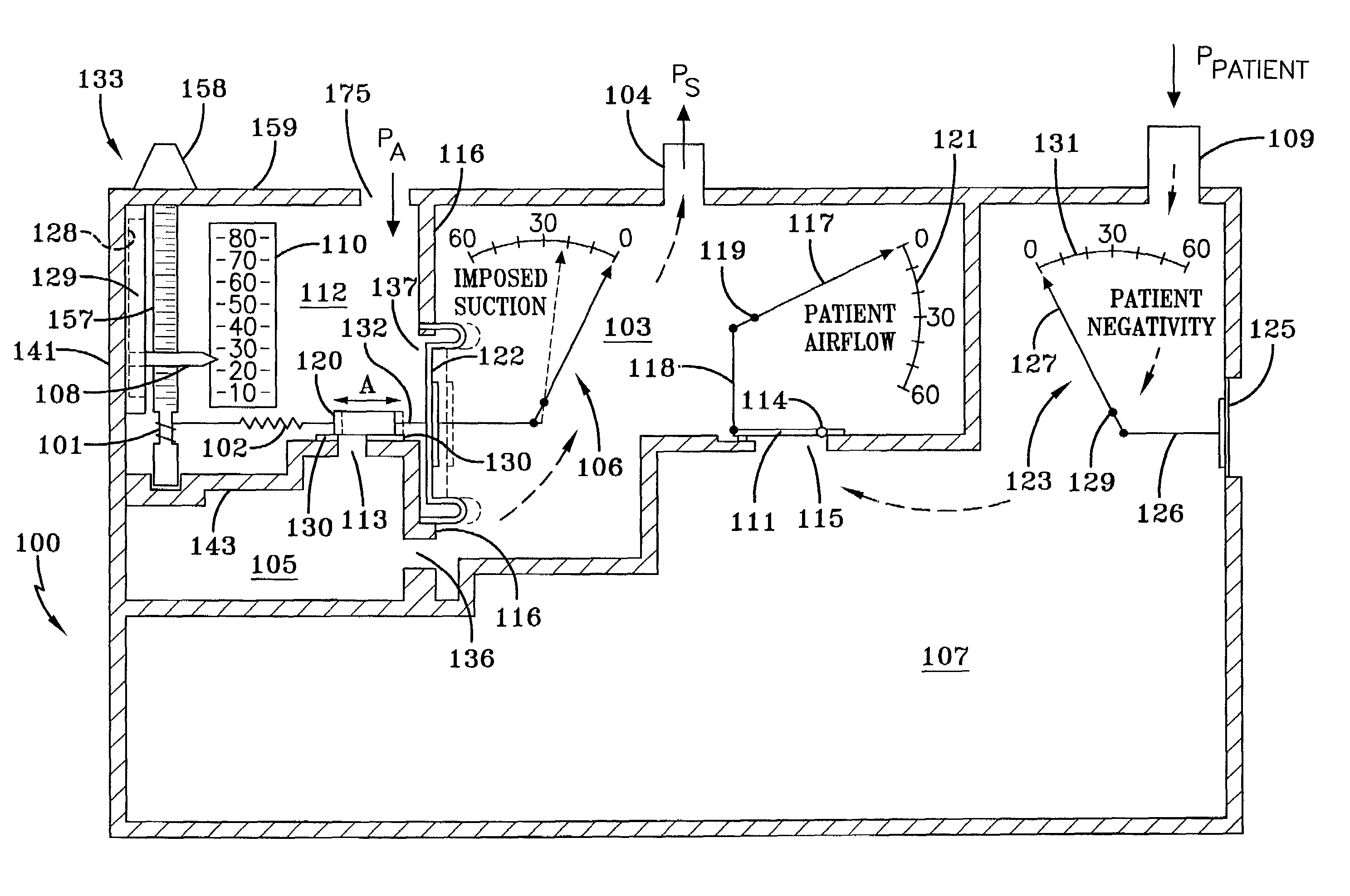
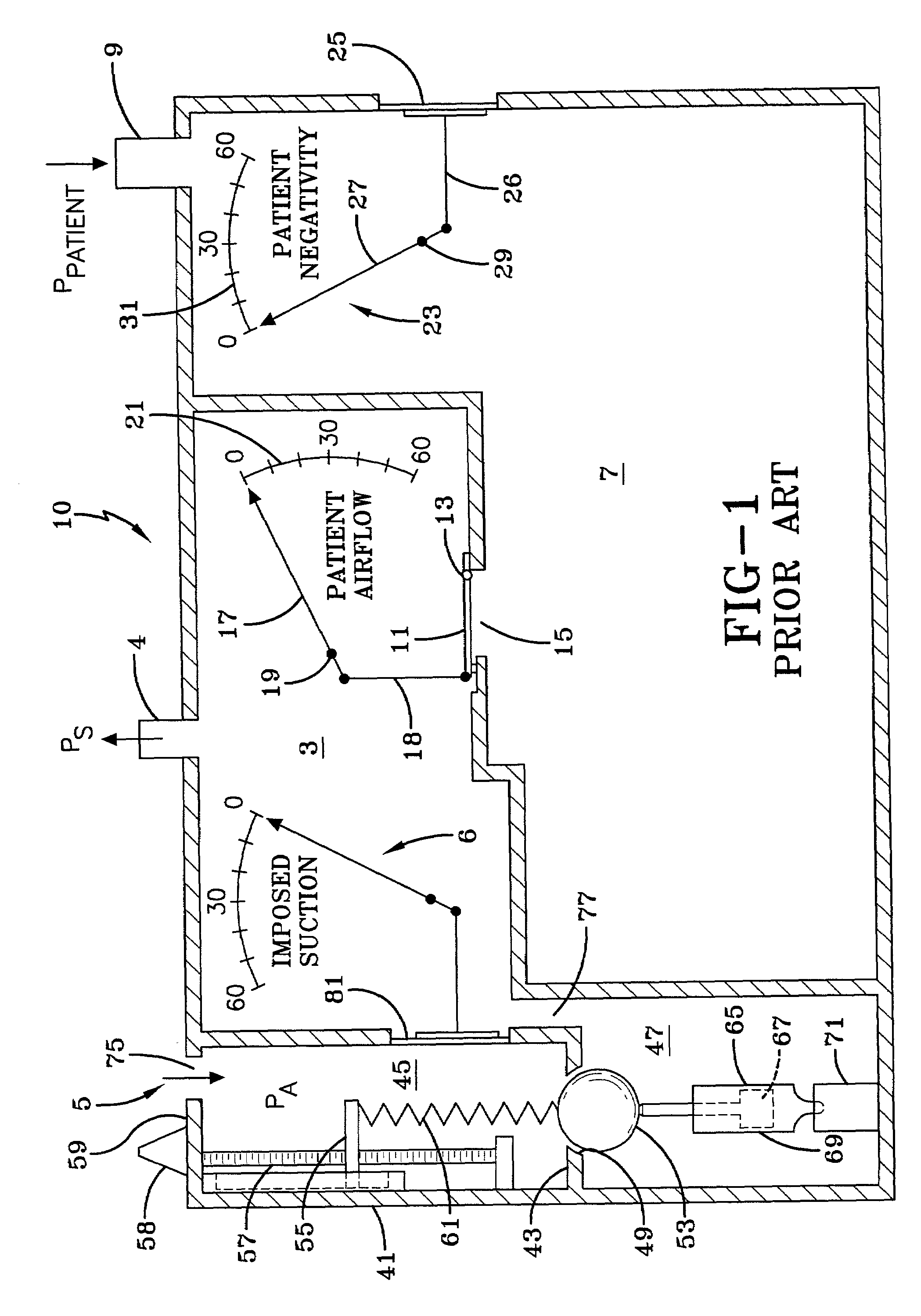
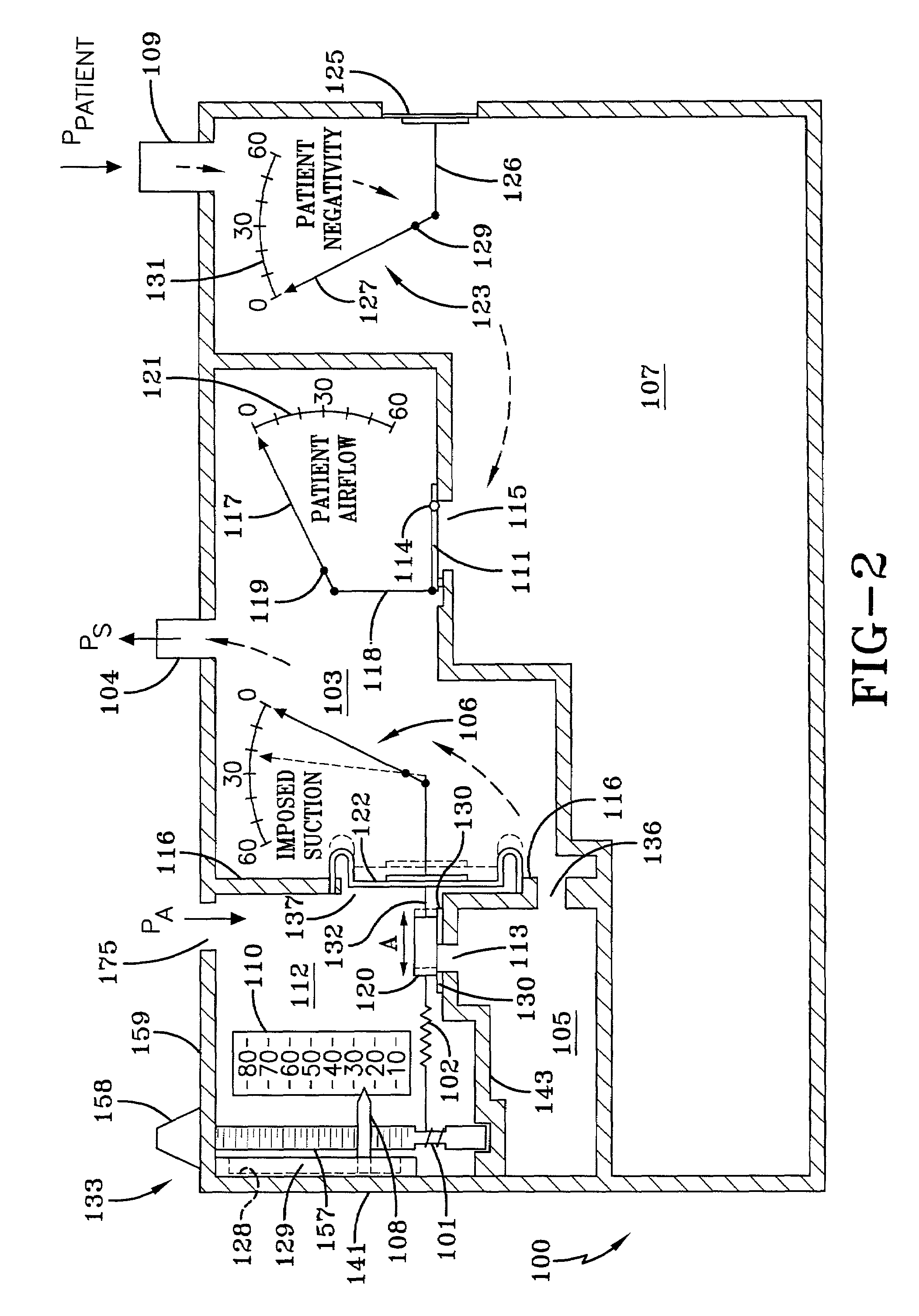
[0023]The figures and description to follow are primarily intended to illustrate the concept for a new, simplified, and more economical suction regulator, and in particular, for its use as a source of dry suction in a chest drainage device. FIG. 1 is a drawing taken from the prior art patents discussed above and included herein for reference, and provides a view of the earlier dry regulator for easy comparison to the present disclosure herein. It is noted that FIG. 1, and all the figures to follow, show a single chamber for the collection of fluids; however, the collection chamber is typically divided into smaller sections for better resolution when reading the value of fluid collected, wherein each of the collection chamber sections can be provided with anti-spill over capability between compartments as the volume collected increases. One such anti-spill over device is that disclosed in U.S. Pat. No. 4,902,284, included herein by reference. Further, the drawings are not shown in th...


PUM


Abstract

A low cost suction regulator is disclosed in conjunction with a fluid drainage system that includes a suction chamber and a collection chamber. The suction regulator is comprised of an atmospheric chamber and a suction chamber separated by a divider. An opening in the divider has a variably biased closing member associated therewith for opening or closing the opening according to operator selected pressure differentials between the chambers. The closing member is movable along an axis that differs from the direction of airflow, thus eliminating the need for damping the forces applied to the closing member. The dividing means and its closing member will operate over the full range of angles from the vertical to horizontal axis. One embodiment of the drainage system further includes devices for measuring patient airflow, patient negativity and imposed suction. Measurement of these variables is effectively implemented with diaphragms or bellows having dials or other types of marker connected thereto such that movement of the diaphragm or bellows results in movement of the dial or marker to thereby indicate the value of the above noted variables.

Description

CROSS REFERENCE TO RELATED APPLICATION[0001]This application claims priority of U.S. Provisional Application No. 60 / 306,024, filed Jul. 17, 2001, under Title 35, United States Code, Section 119(e).BACKGROUND OF THE INVENTION[0002]1. Field of the Invention[0003]This invention relates to fluid pressure regulating systems, such as systems for regulating the pressure of gas. The invention further relates to controlling the pressure of suction flow lines and suction chambers, and in particular as applied to wound drainage systems, for draining fluids from medical patients, such as from the chest cavity, by means of gas pressure differentials using low pressure gas systems.[0004]2. Description of the Prior Art[0005]In many situations involving gases, it is important, and often mandatory, to measure and regulate the pressure of the gas. In one important example, there exists in hospitals a system for distributing vacuum or suction from a central vacuum supply system, which in many cases mu...

Claims


Application Information

Patent Timeline
IPC IPC(8): A61M1/00
CPCA61M1/0013A61M1/0023A61M1/0027A61M1/0025Y10T137/7897Y10T137/7793A61M1/73A61M1/61A61M1/732A61M1/743A61M1/734
Inventor D'ANTONIO, NICHOLAS F.
Owner DANTONIO CONSULTANTS INT INC
Why Eureka
Try Eureka