Pad assembly for disc brake

a technology for disc brakes and pads, applied in the direction of braking elements, slack adjusters, braking members, etc., can solve the problems of difficult to achieve desired sliding characteristics with respect to the rear surface of shim plates, and easy generation of brake noise, so as to achieve smooth sliding, prevent uneven wear of pads, and facilitate movement of calipers

Active Publication Date: 2006-07-20
AKEBONO BRAKE IND CO LTD
View PDF5 Cites 31 Cited by
  • Summary
  • Abstract
  • Description
  • Claims
  • Application Information

AI Technical Summary

Benefits of technology

[0012] In the pad assembly for a disc brake having the above-described structure according to the one or more embodiments of the present invention, the outer shim plate, or the other member between the inner and outer shim plates, is smoothly slidable in the circumferential direction of the rotor with respect to the inner shim plate. Therefore, even though the pad moves in the circumferential direction of the rotor by the rotor during braking, the movement of caliper can be stable, and thus uneven wear of the pad and the noise of brake can be prevented.
[0013] Moreover, in accordance with the one or more embodiments of the present invention, the plurality of the outer locking pieces which are bent in the same direction as the inner locking pieces are superimposed on the plurality of the inner locking pieces which are bent toward one side of the inner shim plate to lock an outer peripheral surface of the pressure. Accordingly, the outer shim plate is prevented from being separated from the inner shim plate in the axial direction of the rotor. As a result, workability of mounting the pad assembly, consisting of the respective shim plates and the pad, on the disc brake can be improved.
[0014] In addition, after the inner shim plate is mounted on the pressure plate by using the respective inner locking pieces, the inner locking pieces are locked with the outer locking pieces in the axial direction of the rotor. Thus, the outer shim plate can be guided to move in the circumferential direction of the rotor with respect to the inner shim plate. Further, the inner locking pieces can make the inner shim plate to lock the pad. Accordingly, it is possible to have a fewer number of bent parts for the inner and outer shim plates, and thus the cost of the disc brake can be decreased.
[0018] In the structure, a length in the axial direction of the rotor of the main body part, between the farthest part from the center in the radial direction of the rotor of the inner shim plate on the outer surface of the pair of the inner locking pieces and the outer surface of the main body part of the inner shim plate, and a length in the axial direction of the rotor of the main body part, between the closest part to the center in the radial direction of the rotor of the outer shim plate on the inner surface of the pair of the outer locking pieces and the inner surface of the main body part of the outer shim plate, are properly regulated. Therefore, the outer shim plate is prevented from being separated from the inner shim plate. As a result, workability of mounting the pad assembly, consisting of the respective shim plates and the pad, on the disc brake can be improved.
[0020] In addition, in accordance with one or more embodiments of the present invention, a fastening margin, between the respective outer locking pieces and the respective inner locking pieces which are additionally provided on the pressure plate (in a state in which the inner shim plate and the outer shim plate are mounted on the pressure plate), may be set to be substantially zero. In the structure, the outer shim plate can be smoothly movable in the circumferential direction of the rotor with respect to the inner shim plate without rattling.

Problems solved by technology

Accordingly, a movement of the caliper becomes in an unstable state, and thus, uneven wear is likely to occur in a lining of the pad in the circumferential direction.
When the uneven wear occurs, the pad rapidly reaches a wear threshold or the surface pressure applied between the pad and the rotor becomes uneven in the circumferential direction, so that the noise of a brake can be easily generated.
However, in the disc brake, if the rear surface of the pressure plate has low roughness precision (rough), it is hard to achieve desired sliding characteristics with respect to the rear surface of the shim plate, and thus the above-described effect cannot be achieved.
Accordingly, the whole structure of the inner and outer shim plates 1 and 2 should have a number of bent parts, and the bent parts are not uniformly bent in one direction, which causes cost to increase.

Method used


Image

  • Pad assembly for disc brake
  • Pad assembly for disc brake
  • Pad assembly for disc brake

Examples


first embodiment

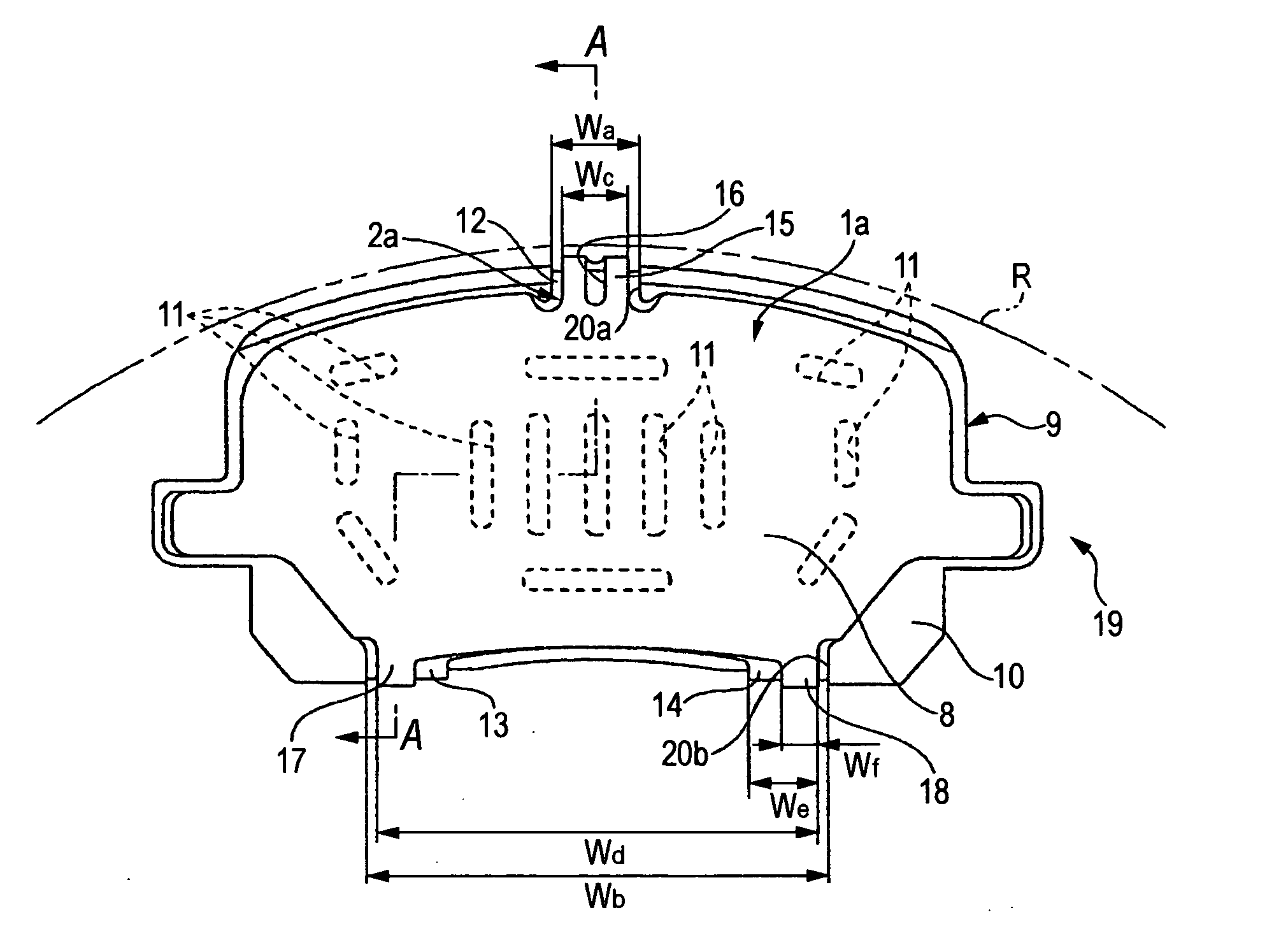
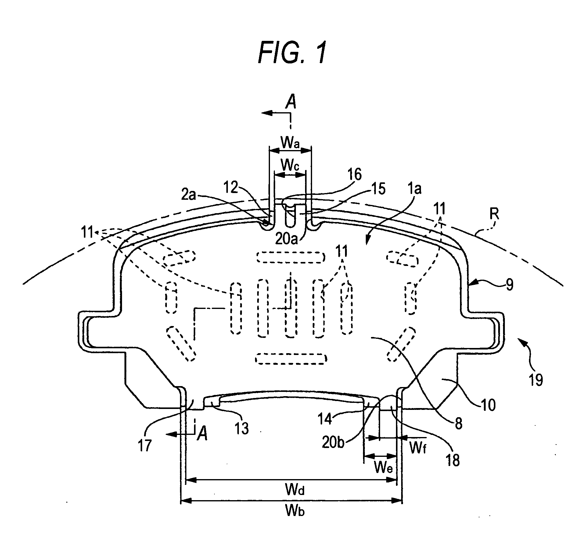
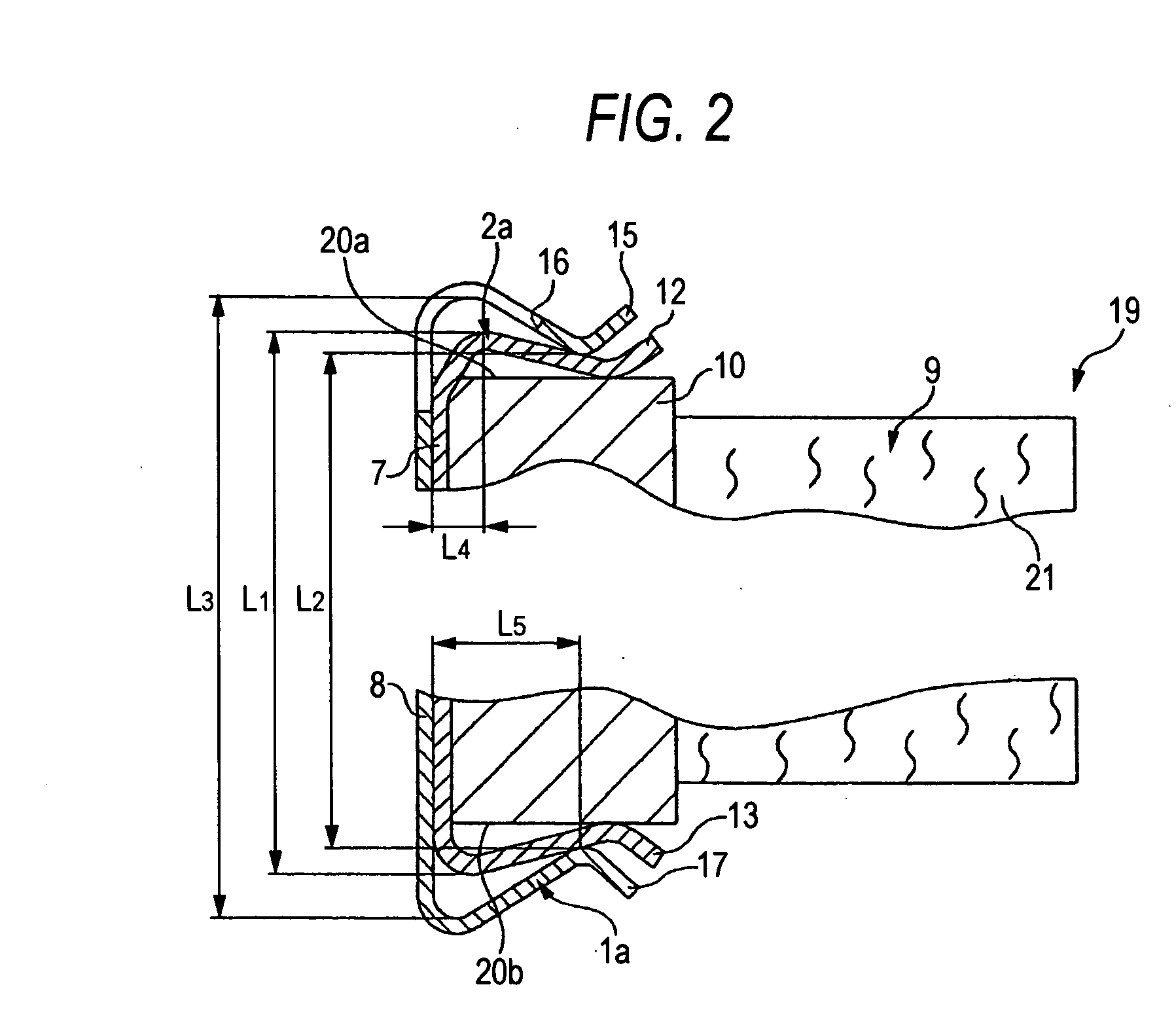
[0050] A first embodiment of the invention will be described with reference to FIGS. 1 to 3. A pad assembly 19 for a disc brake according to the present embodiment is provided with an inner shim plate 2a additionally provided at a rear surface (right side surface of FIG. 2) of a pressure plate 10 of a pad 9, and an outer shim plate 1a whose main body part 8 is directly superimposed on a main body part 7 of the inner shim plate 2a. The inner shim plate 2a is made of metal materials such as stainless steel like SUS301-CSP. One surface (rear surface of FIGS. 1 and 3, right surface of FIG. 2) of the main body part 7 of the inner shim plate 2a is coated with NBR-based rubber. Perforation holes 11 and 11 are formed in a plurality of places of the main body part 7 in an axial direction of a rotor which is indicated by R, that is, a width direction of the main body part 7.

[0051] An outer end in a rotor radial direction, that is, an end (upper end of FIGS. 1 to 3) in a height direction of t...

second embodiment

[0066] Next, FIG. 4 shows a second embodiment of the invention. Unlike the above-described first embodiment, in the second embodiment, one intermediate shimplate 22 is interposed between the main body part 7 of the inner shim plate 2a and the main body part 8 of the outer shim plate 1a. The intermediate shim plate 22 is formed of metal materials such as stainless steel like SUS301-CSP in at a bular'shape. At least one of the shim plates 22 and 2a is coated with grease such that grease is interposed between the intermediate shim plate 22 and the inner shim plate 2a. Further, at least one of the shim plates 22 and 1a is coated with grease such that grease is interposed between the intermediate shim plate 22 and the outer shim plate 1a.

[0067] In the present embodiment having the above-described constitution, the outer shim plate 1a can be smoothly sliding with respect to the intermediate shim plate 22. Further, since a pad assembly 19a is formed by mounting three shim plates 1a, 22 an...


PUM


Abstract

First to third inner locking pieces 12 to 14 are provided at both ends of an inner shim plate 2a in a radial direction of a rotor so as to be bent toward the pad, respectively. First to third outer locking pieces 15, 17 and 18 are provided at both ends of an outer shim plate 1a in the radial direction of the rotor so as to be bent in the same direction as the locking pieces 12 to 14. An inner shim plate 2a is mounted on a pressure plate 10, and the first to third outer locking pieces 15, 17 and 18 are superimposed on the first to third inner locking pieces 12 to 14 such that main body parts 7 and 8 of the respective shim plates 2a and 1a are locked in the pad in the axial direction of the rotor.

Description

[0001] The present application claims foreign priority based on Japanese Patent Application No. P.2005-010063, filed on Jan. 18, 2005, the contents of which are incorporated herein by reference. BACKGROUND OF THE INVENTION [0002] 1. Field of the Invention [0003] The present invention relates to a pad assembly for a disc brake, which is assembled in a disc brake of a vehicle, for preventing a noise of braking and uneven wear of a pad. [0004] 2. Related Art [0005] In order to prevent a noise of a disc brake and uneven wear of a pad, there is a disc brake in which a shim plate is provided between a claw portion of a caliper and a front end surface of a piston, and the pad. When the claw portion of the caliper and the front end surface of the piston are directly brought into contact with a rear surface of a pressure plate constituting the pad, accompanying the pad which moves in a circumferential direction of a rotor while braking, the caliper has tendency to move in the circumferential...

Claims


Application Information

Patent Timeline
Patent Type & Authority Applications(United States)
IPC IPC(8): F16D65/04
CPCF16D65/092F16D65/0979F16D65/0971
Inventor TSURUMI, HIDETOSHISASAKI, TAKAAKI
Owner AKEBONO BRAKE IND CO LTD
Why Eureka
Try Eureka