Resource reservation in a ring network

a resource reservation and ring network technology, applied in the field of communication networks, can solve the problems of node selection method, protocol does not provide any means or basis for automatically updating costs,

Inactive Publication Date: 2005-11-08
ORCKIT IP LLC
View PDF12 Cites 5 Cited by
  • Summary
  • Abstract
  • Description
  • Claims
  • Application Information

AI Technical Summary

Benefits of technology

[0008]It is an object of the present invention to provide improved methods and apparatus for managing resource allocation in a network, and particularly in a network that is arranged in a ring topology.

Problems solved by technology

SRP allows nodes to choose whether to route their packets on the inner or the outer ring, but it does not provide any method for nodes to use in deciding which ring to choose.
Moreover, since the costs are assigned statically by the system administrator, the protocol does not provide any means or basis for updating the costs automatically, while the network is running, in response to network resource constraints.

Method used


Image

  • Resource reservation in a ring network
  • Resource reservation in a ring network
  • Resource reservation in a ring network

Examples


Embodiment Construction

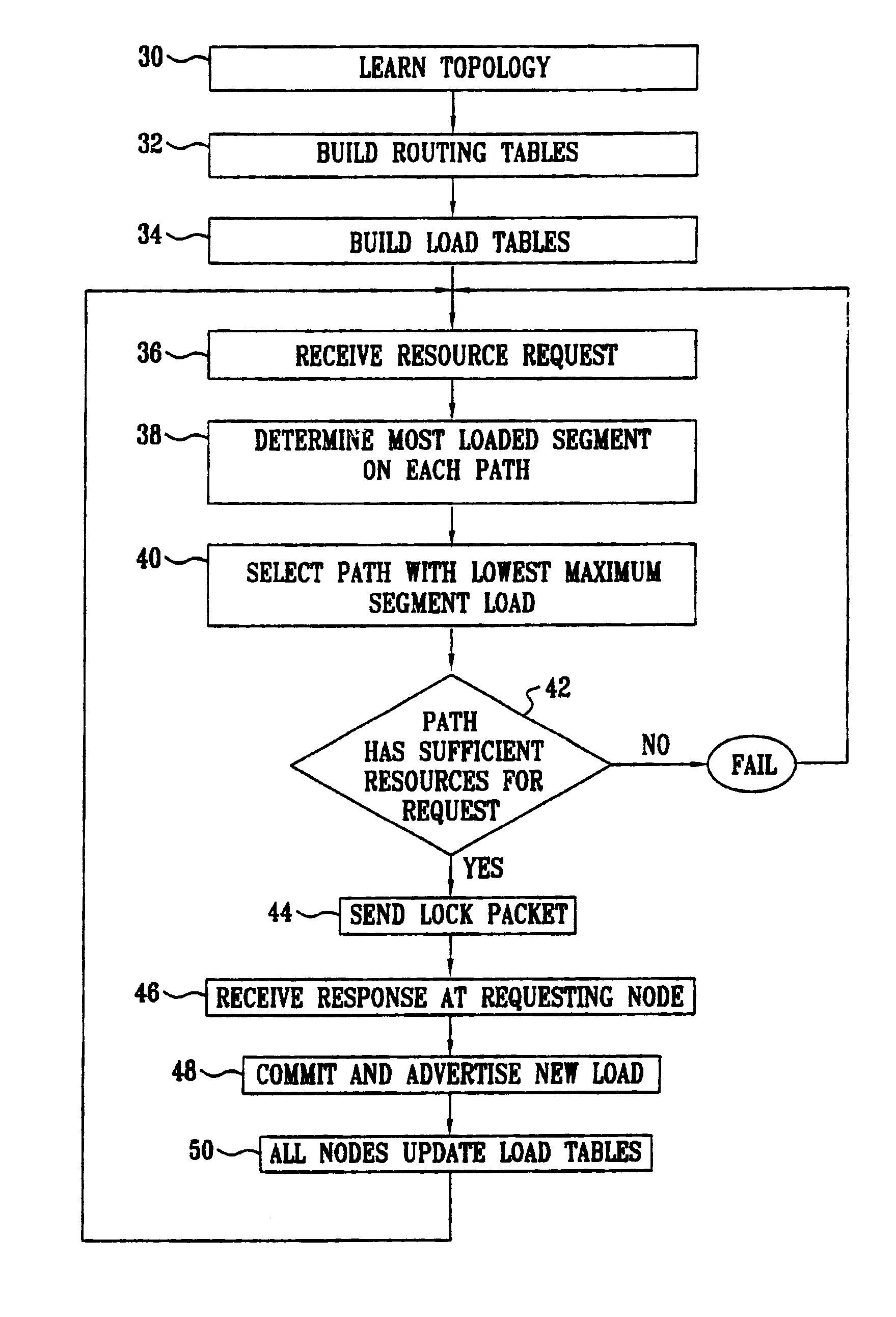
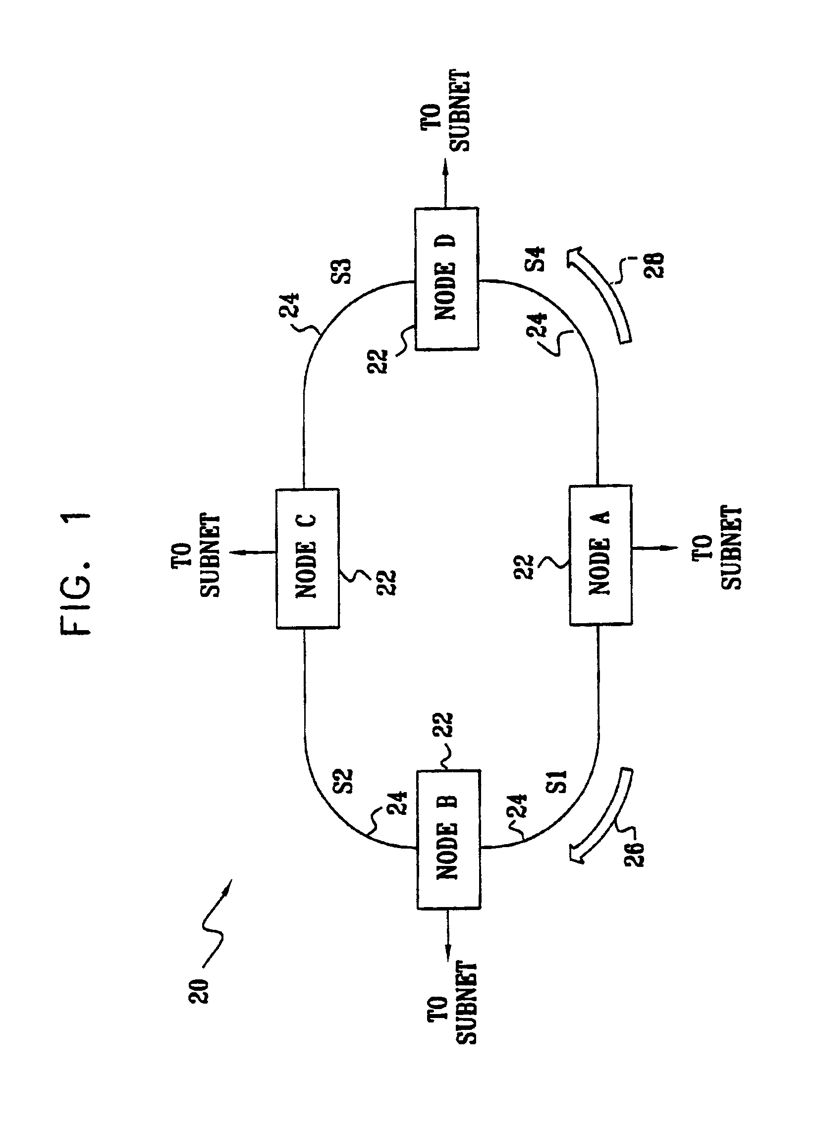
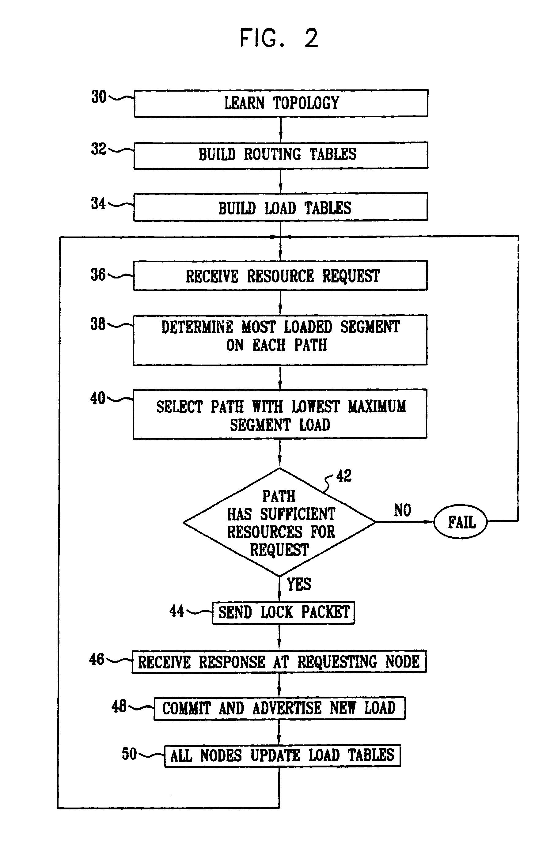
[0030]FIG. 1 is a block diagram that schematically illustrates an IP ring network 20, in accordance with a preferred embodiment of the present invention. Network 20 comprises nodes 22, which are connected by links 24 labeled S1 through S4. Each node can communicate with every other node over either a clockwise ring 26 or a counterclockwise ring 28 around the ring, indicated respectively by arrows adjacent to node A. Following SRP convention, these two paths are identified respectively as an outer ring and an inner ring, each of which is made up of ring segments corresponding to the physical links between the nodes. Typically, each of the nodes also links the ring to a respective subnet, which may be of substantially any topology known in the art. When node A, for example, receives a data flow from its respective subnet, which is destined for the subnet of node C, node A determines whether to transmit the flow over ring 26 or ring 28, using the method described hereinbelow.

[0031]FIG....


PUM


Abstract

A method for routing a data flow from a source node to a destination node among a plurality of nodes mutually linked in a ring by segments of a communication network, configured so that the data flow can traverse the ring in either of first and second, mutually-opposing directions of communication. The method includes maintaining at each of the nodes a record of respective levels of use of a network resource on the segments in the ring for both the first and second directions of communication. Responsive to the respective levels of use, one of the directions is selected at the source node, in which to route the data flow to the destination node. A notification is sent from the source node to the other nodes in the ring of an additional allocation of the resource required by the source node in order to convey the data flow to the destination node in the selected direction on the segments in the ring. The record of the levels of use of the resource at each of the nodes is updated, responsive to the notification from the source node.

Description

CROSS-REFERENCE TO RELATED APPLICATION[0001]This application claims priority of U.S. Provisional Application No. 60 / 221,037, filed Jul. 27, 2000 and U.S. Provisional Application No. 60 / 222,698, filed Aug. 2, 2000.FIELD OF THE INVENTION[0002]The present invention relates generally to communication networks, and specifically to methods and systems for efficient allocation of resources for data flow in such networks.BACKGROUND OF THE INVENTION[0003]Network ring topologies are gaining in popularity, particularly in Internet Protocol (IP) networks. Such networks enable carriers to offer large bandwidth to users in a cost-effective manner. In order to gain these benefits, however, IP needs appropriate support at the Media Access Control (MAC—protocol layer 2) level, to provide functions such as load balancing, protection and clock synchronization.[0004]One solution that has been proposed to meet these needs is the Spatial Reuse Protocol (SRP), which is described by Tsiang et al., in Reque...

Claims


Application Information

Patent Timeline
Patent Type & Authority Patents(United States)
IPC IPC(8): H04L12/56H04L12/433H04L12/423H04L12/427
CPCH04L12/423H04L12/433H04L12/5695H04L45/02H04L47/13H04L47/15H04L47/724H04L47/822H04L47/829H04L47/70
Inventor MOR, GALGRINFELD, RON
Owner ORCKIT IP LLC
Why Eureka
Try Eureka