Electric rotary grater

a rotary grater and electric technology, applied in the field of graters, can solve the problems of difficult and tiresome handling, inapplicability of manual methods to produce large quantities of powder, and limited powder production, and achieve the effect of quick grating and fun for chucking food into powder, and prolonging the life of its us

Inactive Publication Date: 2005-11-22
PAI
View PDF5 Cites 22 Cited by
  • Summary
  • Abstract
  • Description
  • Claims
  • Application Information

AI Technical Summary

Benefits of technology

[0007]The primary objective of the present invention is to provide an electric grater that quickly grates chucks of food into powder with fun. Both hands can operate the grater, thus the user will not feel tired. Furthermore, the power and transmission devices are not in direct contact with the food thus requiring no cleaning after the grating and extending the life of its use. Further, the blade section at the top of the stirring plate of the roller can precut the food, so that the chucks of food can fall into the chambers on both sides, and can overcome the shortcoming of having a small opening of the food feeder for grating a large quantity of food. The grater disc is installed inside the external cylinder and will not be touched by users accidentally to assure the safety of its use. The present invention is definitely a great idea for products of this type.

Problems solved by technology

However, such manual method is not applicable for producing a large quantity of powder.
However, the shortcoming of an electric grater resides on that the opening of the feeder is too small, and food must be sliced first before being put into the feeder for the grating, and thus it can only produce limited quantity of powder.
The palm of a housewife is usually small, which makes the handling difficult and tiresome.
Moreover, if the pressing board is not operated with care, it may clamp and hurt a user's hand, which bother users very much.

Method used


Image

  • Electric rotary grater
  • Electric rotary grater
  • Electric rotary grater

Examples


Embodiment Construction

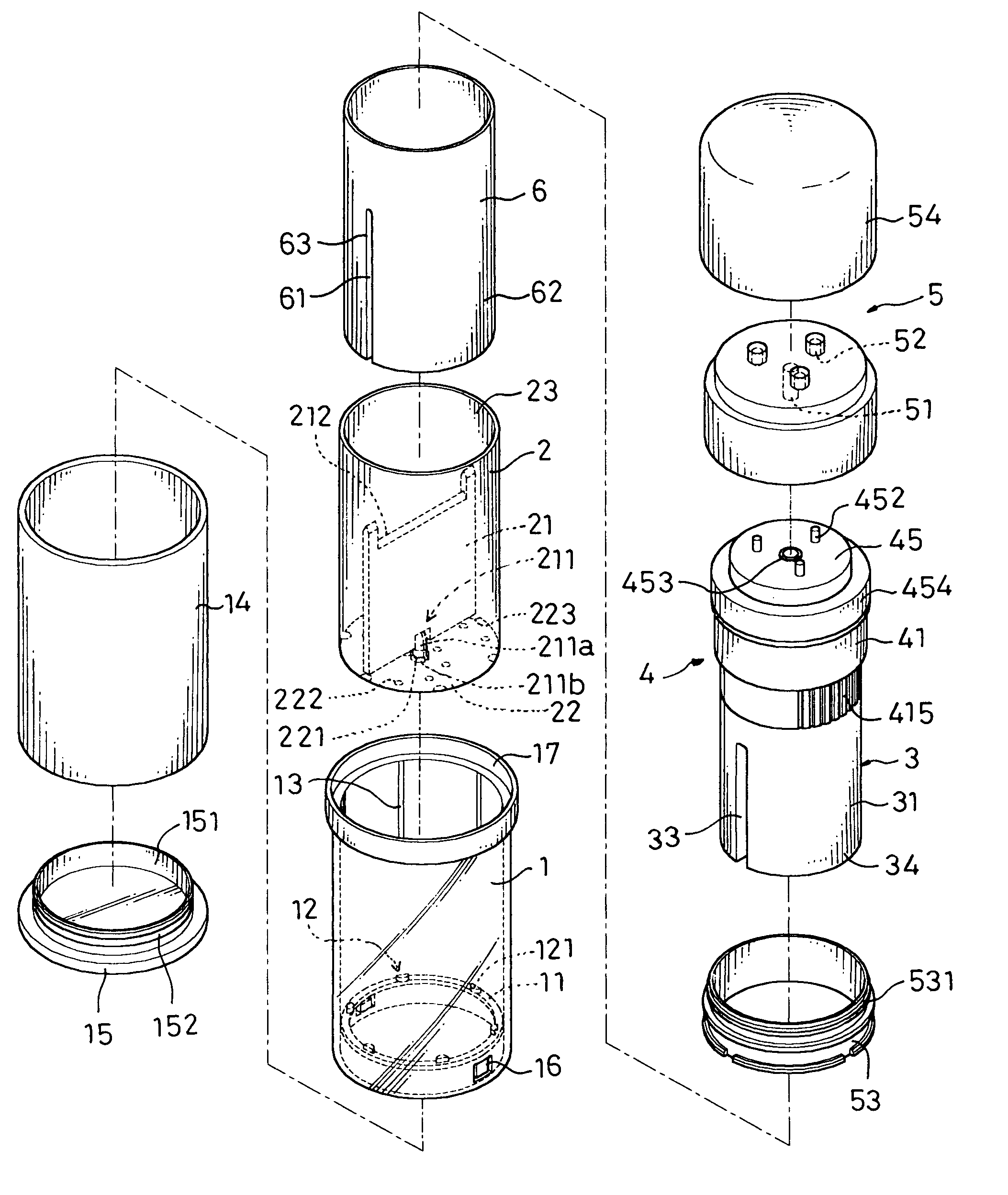
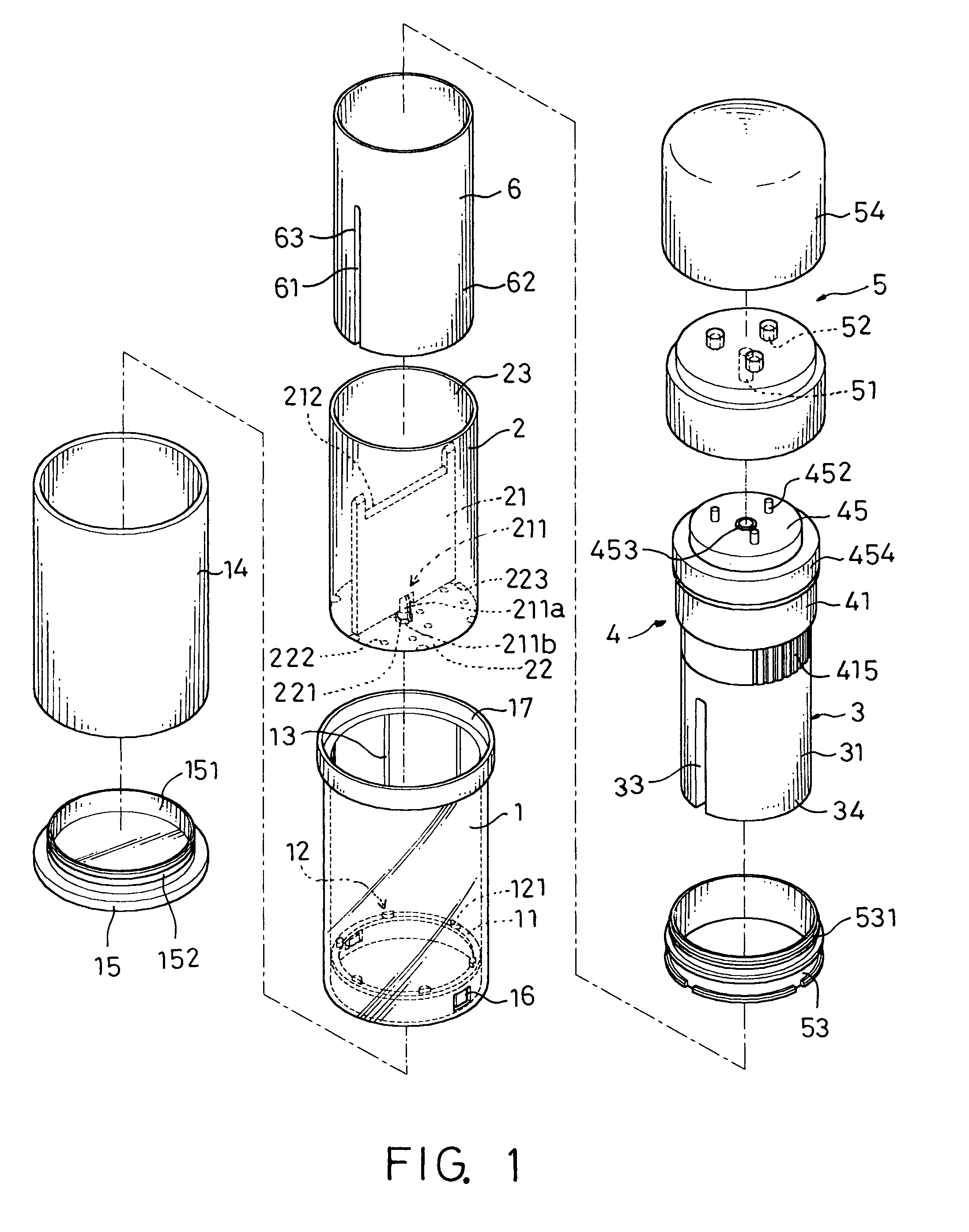
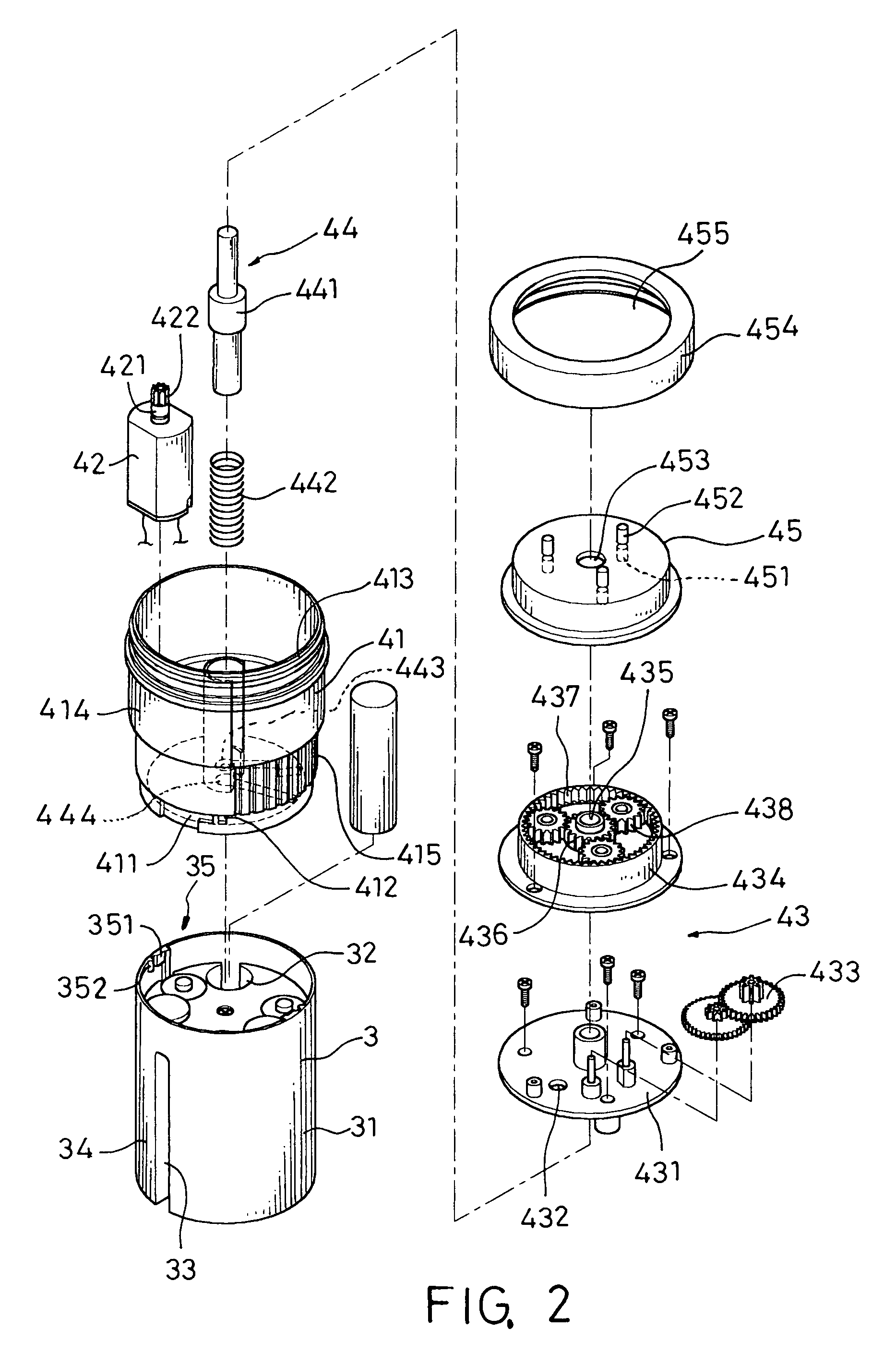
[0013]Refer to FIGS. 1 to 3 for the grater of the present invention, which comprises an external cylinder 1, a roller 2, a power device 3, a transmission device 4 and a top cover 5.

[0014]The external cylinder 1 is a hollow cylinder having a blocking edge 11, a positioning mechanism protruded from the bottom of an inner wall of the external cylinder 1 as shown in FIG. 1 and a plurality of tenons 12 protrude from the blocking edge 11 for coupling with the grooves 223 at the periphery of a grater disc 22. The grate disc 22 is fixed onto the bottom of the external cylinder 1. To reduce the friction between the inner walls of the external cylinder 1 and the roller 2, a plurality of transversal ribs 13 are built on the inner wall, so that the roller 2 can rotate smoother. In addition, a metal pipe such as an external stainless steel pipe is sheathed onto the exterior of the external cylinder 1 to enhance the external texture of the grater of the present invention. Further, a bottom chassi...


PUM


Abstract

An electric rotary grater including an external cylinder and a roller being sheathed into the external cylinder and having a stirring plate connected to a blocking edge of the external cylinder. A chamber is defined each on both sides of the stirring plate which is connected to a grater disc having a plurality of grater holes. A power device having a power source disposed in a housing, and a pillar groove transversally disposed outside the housing into which the stirring plate is inserted and a housing pillar on both sides of the pillar groove. A transmission device being connected to the power device and having a motor, a retardation mechanism and a press switch in the housing. A top cover presses on a driven set assembly to make planet gears of the retardation mechanism run in idle and the housing and shell to rotate and thus driving the roller to rotate.

Description

BACKGROUND OF THE INVENTION[0001]1. Field of the Invention[0002]The present invention relates to a grater, more particular to an electric rotary grater.[0003]2. Description of the Related Art[0004]In western cuisines, chunks of cheese or chocolate are generally grated into powder and spread onto food to give better flavors to the food. The common graters usually have grater holes stamped out from a piece of metal plate, and the food is held by a hand and grated back and forth on the grater into powder. However, such manual method is not applicable for producing a large quantity of powder.[0005]Therefore, grater manufacturers started developing electric graters to grate cheese or chocolate into powder in a more efficient and quicker way. The “KRUPS” branded cheese grater is an example of such electric grater. However, the shortcoming of an electric grater resides on that the opening of the feeder is too small, and food must be sliced first before being put into the feeder for the gra...

Claims


Application Information

Patent Timeline
Patent Type & Authority Patents(United States)
IPC IPC(8): A47J43/00A47J43/25H02K7/14H02K7/116
CPCA47J43/255H02K7/116H02K7/14
Inventor PAI, CHUNG-JEN
Owner PAI
Why Eureka
Try Eureka