Method and device for recording information in units

a technology of information and unit, applied in the field of method and device for recording information in units, can solve the problems of hardly being able to start recording process, decoding will be confronted with a shift of symbol boundary, damaged modulated signal at the first location, etc., and achieve the effect of preventing disturbing the value of read signal and low error number

Inactive Publication Date: 2005-11-22
KONINK PHILIPS ELECTRONICS NV
View PDF6 Cites 20 Cited by
  • Summary
  • Abstract
  • Description
  • Claims
  • Application Information

AI Technical Summary

Benefits of technology

[0008]It is an object of the invention to provide a recording method and device in which linking is more efficient.
[0010]Further, the device as described in the opening paragraph is characterized in that the recording means determines if the second one of said locations is after and adjacent to the first one of said locations, and, in such event, starts the recording before the end of a last frame of the earlier recorded information signal at a first predefined distance before a first synchronizing signal of the modulated signal. By starting the recording within the last part of the earlier recorded signal, the signal in the next, adjacent area, i.e., said second location, is positioned at the nominal position and includes, completely, the first synchronizing signal as required by decoding circuits to decode the new data recorded at the second location. Hence, the modulated signal at the second location is completely decodable. In fact, the link position is located within the existing recorded information, and, consequently, the modulated signal at the first location is damaged in the very last part. Although this causes a few errors in the last symbols of the earlier recorded information unit, this proves to be preferable to losing an entire linking block. The errors may be acceptable for the system, or a system of error protection may be applied to correct these errors. The measures according to the invention have the advantage that no linking block is created and no storage capacity is lost, because the second location, comprising the last recorded signal, is directly adjacent to the first location comprising the previously existing signal. In addition, any recorded data stream is not interrupted by invalid data from the linking block, which provides better compatibility with existing read-only record carriers, e.g. DVD-ROM or DVD-VIDEO.
[0012]A preferred embodiment of the device, wherein the recording means terminates the recording before the modulated signal is completely recorded at a second predefined distance before a nominal position of a first synchronizing signal of an information signal at the subsequent one of said locations, has the advantage, in the event that a new recording is to be made before and adjacent to an existing one, that the first synchronizing signal of the existing recording is not damaged, and only a predictable and low number of errors is generated when decoding the last recorded signal.
[0013]A preferred embodiment of the device, wherein the recording means variably selects the first predefined distance between a minimum and a maximum value, while maintaining the postion of the first synchronizing signal, has the advantage that the physical starting point of recording is varied. This has the effect that disturbing read signal values are prevented, while the data is not shifted from its actual position.
[0014]A preferred embodiment of the device, wherein the recording means records variable random data in the interval between the predetermined distance and the first synchronizing signal, has the advantage that, by using variable random data instead of a fixed pattern in said interval, the sign of the synchronizing signal is also randomly varied for subsequent overwrite cycles of the same location. Hence, material defects in the recording layer of said location due to repeated writing of the same patterns are counteracted.

Problems solved by technology

In fact, the link position is located within the existing recorded information, and, consequently, the modulated signal at the first location is damaged in the very last part.
When, during decoding, a read signal from the link position is decoded, the decoder will be confronted with a shift of the symbol boundary, a so-called bit slip of a few bits, because it is, in practice, hardly possible to start the recording process with an accuracy of less than one bit.
In prior art systems, this posed no problem, as the linking block did not contain useful data.

Method used


Image

  • Method and device for recording information in units
  • Method and device for recording information in units
  • Method and device for recording information in units

Examples


Embodiment Construction

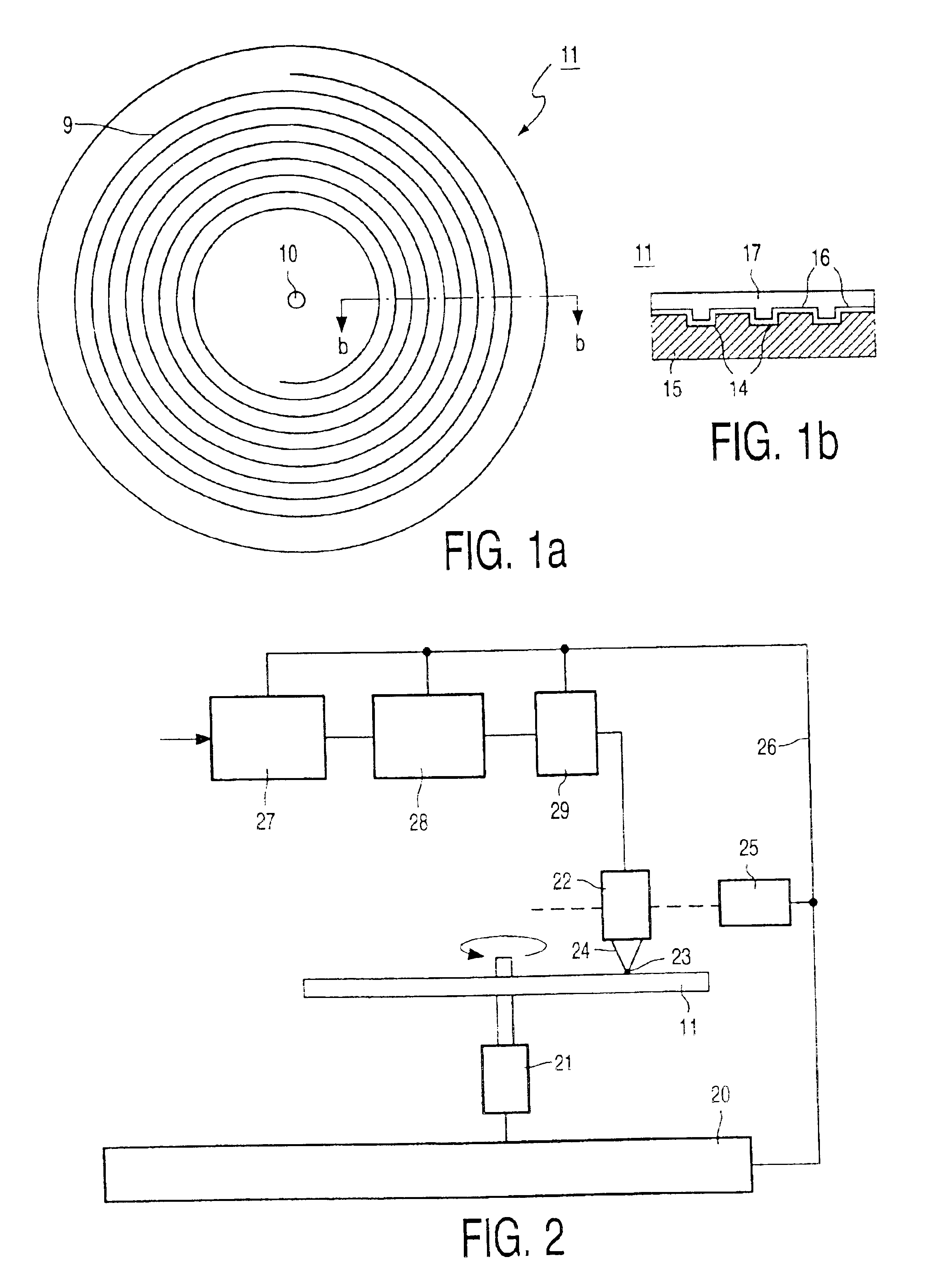
[0027]FIG. 1a shows a disc-shaped record carrier 11 having a track 9 and a central hole 10. The track 9 is arranged in accordance with a spiral pattern of turns, constituting substantially parallel tracks, on an information layer. The record carrier may be optically readable, called an optical disc, and has an information layer of a recordable type. Examples of a recordable disc are the CD-R and CD-RW, and writable versions of DVD, such as DVD+RW. The information is represented on the information layer by recording optically detectable marks along the track, e.g., crystalline or amorphous marks in phase change material. The track 9 on the recordable type of record carrier is indicated by a pre-embossed track structure provided during manufacture of the blank record carrier. The track structure is constituted, for example, by a pre-groove 14 which enables a read / write head to follow the track during scanning. The track structure comprises position information, e.g., addresses, for ir...


PUM

PropertyMeasurementUnit
distanceaaaaaaaaaa
lengthaaaaaaaaaa
predefined distanceaaaaaaaaaa

Abstract

A method and device for recording information signals on a partly recorded writable record carrier (11), e.g., an optical disc. An information signal represents at least one information unit. The record carrier has a recording track which includes pre-formed track position information indicative of locations for recording the information units. From the information signal, a modulated signal is generated having successive frames, each frame including a synchronizing signal. The modulated signal is recorded at a one of the locations, while maintaining a fixed relationship between the track position information and the synchronizing signals. In the event that the location is after and adjacent to an already recorded location, the recording is started at a link position (31) before the end of a last frame of the earlier recorded information signal, at a predefined distance before a first synchronizing signal (30) of the modulated signal.

Description

CROSS REFERENCE TO RELATED APPLICATIONS[0001]This is a continuation application of U.S. pat. Ser. No. 09 / 601,754, filed Aug. 7, 2000, now U.S. Pat. No. 6,628,583.[0002]BACKGROUND OF THE INVENTION[0003]1) Field of the Invention[0004]The invention relates to a method of recording an information signal representing at least one information unit on a record carrier having a recording track comprising pre-formed track position information indicative of predefined locations for consecutively recording the information units, and a first one of said locations comprising an earlier recorded information signal, said method comprising: generating from the information signal a modulated signal having successive frames, each frame including a synchronizing signal, and scanning said recording track and recording the modulated signal at a second one of said locations, while controlling such recording so as to maintain a fixed relationship between the track position information and the synchronizin...

Claims


Application Information

Patent Timeline
Patent Type & Authority Patents(United States)
IPC IPC(8): G11B5/09H04N5/85G11B7/0045G11B7/007G11B20/10G11B20/12G11B20/18G11B27/034G11B27/036G11B27/19G11B27/24G11B27/30G11B27/32G11B27/36H04N5/92
CPCG11B7/0045G11B7/00736G11B20/10G11B20/1217G11B27/034G11B27/24G11B27/3027G11B27/329G11B20/18G11B27/36G11B2020/1222G11B2020/1267G11B2020/1275G11B2020/1277G11B2020/1287G11B2020/1288G11B2020/1289G11B2220/216G11B2220/218G11B2220/2537G11B2220/2545G11B2220/2562G11B7/007G11B20/1833G11B20/00007G11B2020/1225G11B2020/1238G11B2020/00014G11B2020/00072
Inventor VAN DEN ENDEN, GIJSBERT JOSEPH J.SPRUIT, JOHANNES H. M.DRENTEN, RONALD R.ERADUS, JACOBUS M.VAN VLERKEN, JOHANNES J. L. M.BRONDIJK, ROBERT A.IJTSMA, POPE
Owner KONINK PHILIPS ELECTRONICS NV
Why Eureka
Try Eureka