Multi-nozzle ink jet head

Inactive Publication Date: 2005-06-07
FUJIFILM HLDG CORP
View PDF5 Cites 2 Cited by
  • Summary
  • Abstract
  • Description
  • Claims
  • Application Information

AI Technical Summary

Benefits of technology

[0015]It is an object of the present invention to provide a multi-nozzle ink jet head having a diap

Problems solved by technology

With such head formation, in the case of forming thin piezoelectric bodies (<50 μm), there have been problems in that fluctuations in the thickness of the adhesive result in fluctuations in the characteristics, and hence the head driving characteristics deteriorate, and moreover bonding may not be possible (splitting may occur during bonding).
However, with this conventional multi-layer constitution proposal, the functioning of the electrode is improved, but considerat

Method used


Image

  • Multi-nozzle ink jet head
  • Multi-nozzle ink jet head
  • Multi-nozzle ink jet head

Examples


first embodiment

[First Embodiment]

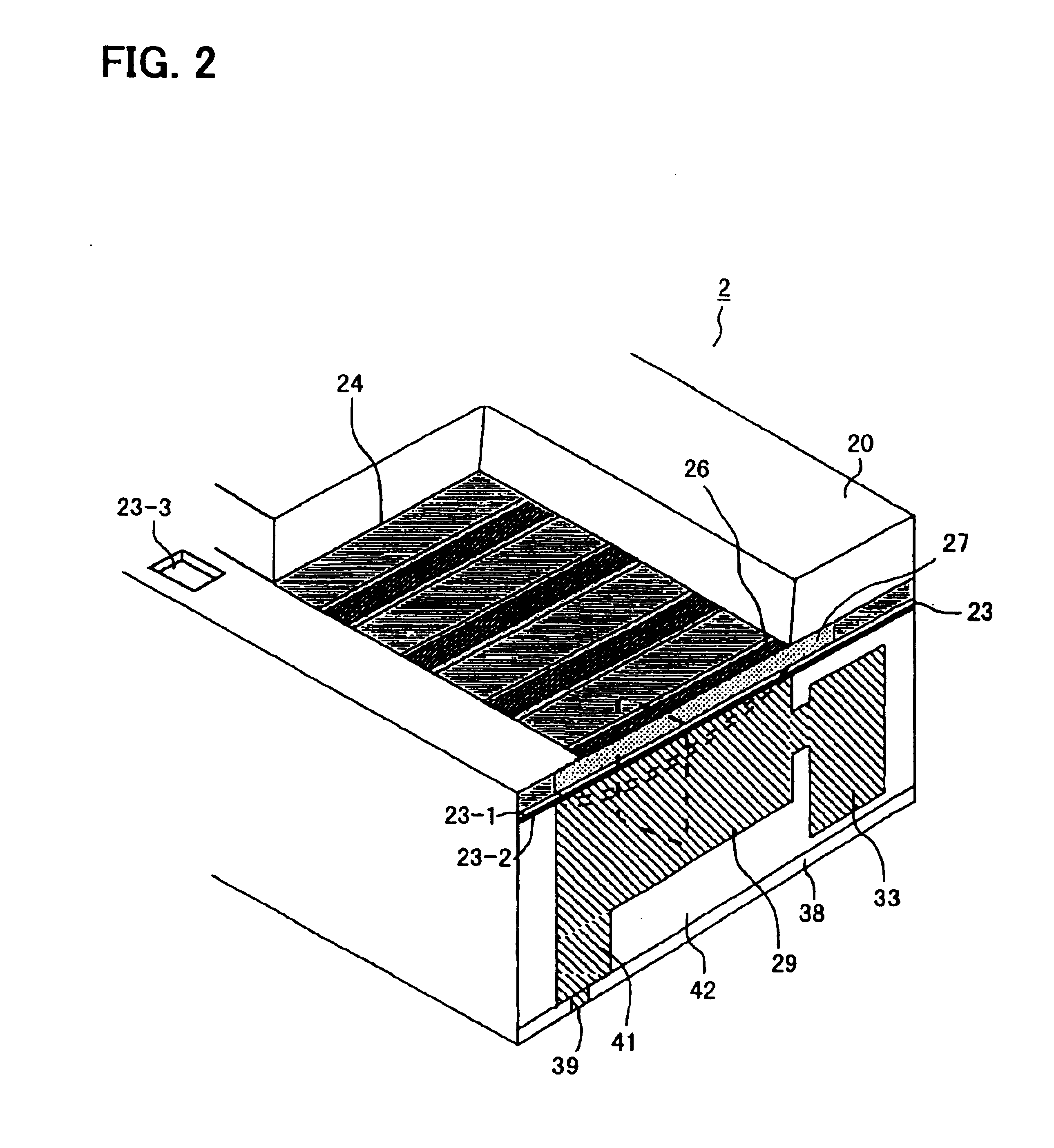
[0078]FIG. 2 is a sectioned perspective view of the ink jet head 2 of a first embodiment of the present invention. Firstly, a description will be given of the constitution of the ink jet head 2 using FIG. 2. Broadly speaking, the ink jet head 2 is constituted from a substrate 20, a diaphragm 23, a main body part 42, a nozzle plate 38, ink ejection energy generating parts (hereinafter referred to as the ‘energy generating parts’) and so on.

[0079]The main body part 42 has a structure in which dry films are laminated as will be described later, and inside thereof are formed a plurality of pressure chambers 29 (ink chambers) and an ink channel 33 that acts as a supply channel for the ink. Moreover, the top part in the drawing of each pressure chamber 29 is made to be a free part, and an ink lead-through channel 41 is formed in the bottom surface of each pressure chamber 29.

[0080]Moreover, the nozzle plate 38 is disposed on the bottom surface in the drawing of the main ...

example 1

[0103]FIG. 6 stipulates the size, material and so on for each element in the specifications of a 150 dpi multi-nozzle head for which the minimum particle amount is made to be 1.5 pl and the driving frequency 20 kHz. The permitted waveform lag with this head is 50 ns. This head is the high-density head of FIG. 2 having a nozzle pitch of 170 μm, with the width of the pressure chambers 29 being made to be 100 μm and the length 700 μm, and the thickness of the piezos (piezoelectric elements) 27 being made to be 1 μm and the width 70 μm.

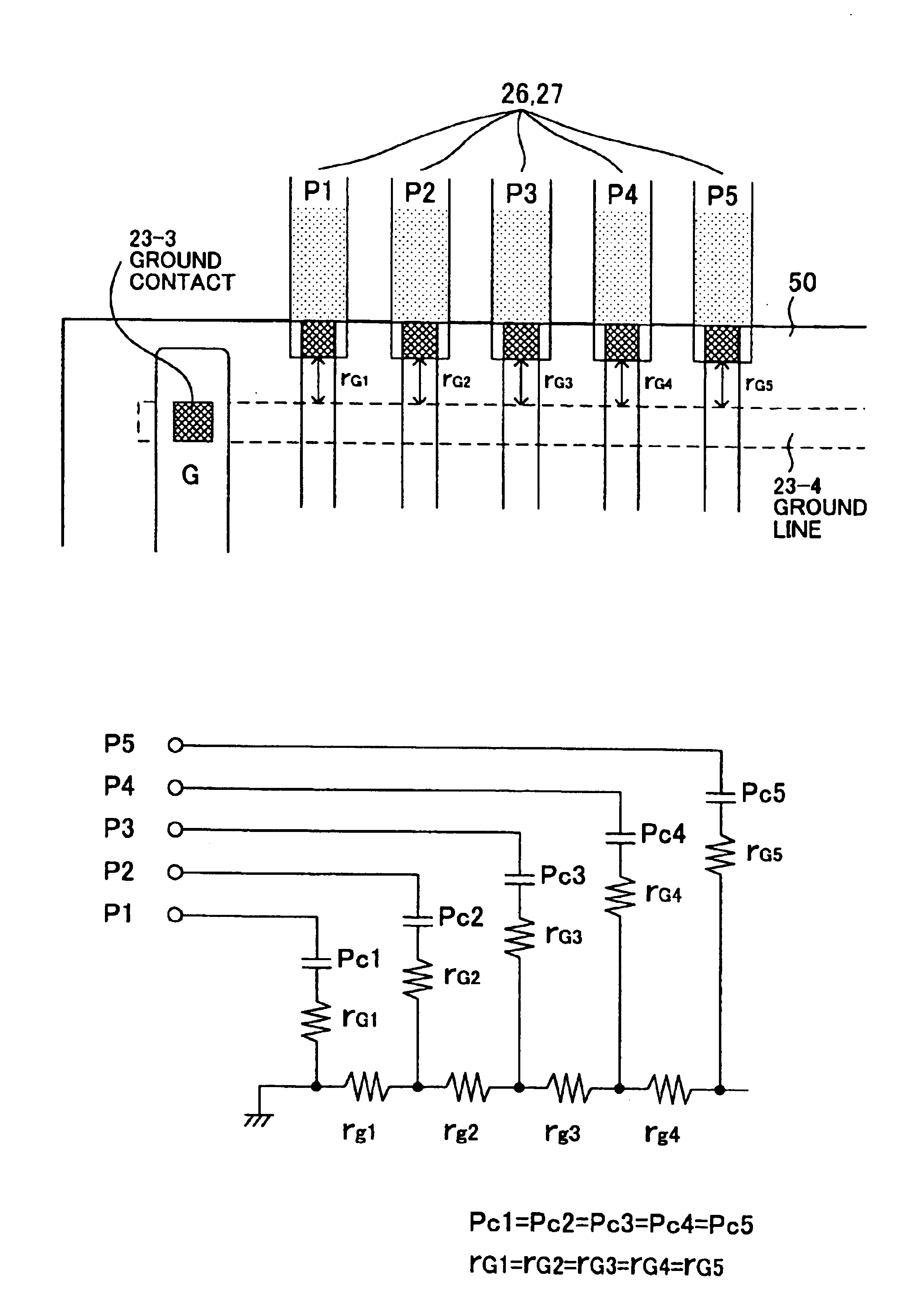
[0104]The capacitance of the piezos was made to be 208.152 pF, and Cr (resistivity 1.27 μΩ·m) was used as the common electrode layer 23-1. The number of nozzles was 64 pins, and a ground contact 23-3 was provided at each end of the row of nozzles. With an applied voltage of 20V, the thickness of the electrode layer 23-1 was changed, and the rise time CR of the driving waveform was calculated.

[0105]Note that a method was adopted in which an earth is led ou...

example 2

[0107]In a 150-dpi head of the constitution of FIG. 6, Ni (resistivity 0.724 μΩ·m) was used as the electrode layer 23-1. FIG. 9 shows calculation results of the resistance value, the waveform rise time 1-CR during 1-pin driving, and the waveform rise time all-CR during all-pin driving for thicknesses of the Ni from 0.1 to 0.35, and FIG. 10 is a graph of these results.

[0108]According to the results, with the Ni electrode layer, because the resistivity is lower than in the case of Cr, there are no electrical problems if the thickness of the electrode layer is about 0.18 μm.

[0109]Next, a method of manufacturing the ink jet head 2 having the constitution described above will be described using FIGS. 11 to 13.

[0110]To manufacture the ink jet recording head 2, firstly a substrate 20 is prepared as shown in FIG. 11(A). In the present example, a magnesium oxide (MgO) monocrystal of thickness 0.3 mm is used as the substrate 20.

[0111]An individual electrode layer 26 (hereinafter referred to m...


PUM


Abstract

A multi-nozzle ink jet head having a diaphragm that effectively utilizes the force generated by thin-film piezoelectric elements is disclosed. The head (2) has a head substrate (28) in which are formed a plurality of nozzles (39) and a plurality of pressure chambers (29), a multi-layer diaphragm (23-1, 23-2), piezoelectric elements (27), and individual electrodes (26). By making the thickness of the common electrode layer (23-1) of the multi-layer diaphragm be thin but such that problems do not occur during multi-pin driving, optimization of the rigid layer becomes possible, and hence it is possible to use the force generated by the thin-film piezoelectric elements efficiently in ink ejection.

Description

[0001]This application is a divisional of U.S. patent application Ser. No. 10 / 254,782, filed Sep. 26, 2002, now abandoned which is a continuation of International Application No. PCT / JP00 / 02137 filed Mar. 31, 2000.TECHNICAL FIELD[0002]The present invention relates to a multi-nozzle ink jet head having a plurality of nozzles, and in particular to a multi-nozzle ink jet head in which are combined thin-film piezoelectric bodies and a diaphragm having a multi-layer structure.BACKGROUND ART[0003]An ink jet head has nozzles, ink chambers, an ink supply system, an ink tank, and transducers. By transmitting displacement / pressure generated by the transducers to the ink chambers, ink particles are ejected from the nozzles, therefore characters or images are recorded on a recording medium such as paper.[0004]In a well-known form, a thin-plate-shaped piezoelectric element having the whole of one surface thereof bonded to the outer wall of an ink chamber is used as each transducer. A pulse-like ...

Claims


Application Information

Patent Timeline
IPC IPC(8): B41J2/045B41J2/04B41J2/14
CPCB41J2/04581B41J2/04588B41J2/14233B41J2002/14491B41J2002/1425
Inventor KOIKE, SHUJISAKAMOTO, YOSHIAKISHINGAI, TOMOHISA
Owner FUJIFILM HLDG CORP
Why Eureka
Try Eureka