Drive arrangement for a motor vehicle door or hatch which can be moved by a motor

a technology for a motor vehicle and a door or hatch is applied in the direction of wing accessories, mechanical equipment, gearing, etc., which can solve the problems of inability to decouple the drive shaft and the driven shaft in an emergency, and inability to achieve the optimal braking action of the drive device, so as to prevent the unexpected slamming of the rear hatch and reduce the braking for

Active Publication Date: 2005-12-15
BROSE SCHLIESSSYSTEME GMBH & CO KG
View PDF9 Cites 20 Cited by
  • Summary
  • Abstract
  • Description
  • Claims
  • Application Information

AI Technical Summary

Benefits of technology

[0021] It is important to this further teaching that, depending on the polarity of the electromagnet, the magnetic field which has been generated by the permanent magnet can be intensified or weakened by means of the electromagnet. In this way, with a comparatively weak design of the electromagnet, a high force acting on the brake in the direction of the braking position-braking force—can be produced.
[0022] In a preferred configuration, the magnetic field generated by the permanent magnet is used to keep the brake in the braking position when the electromagnet has been turned off, in this state the braking force being reduced accordingly. This can be advantageous for temporarily fixing the rear hatch or the like in the opened position or in an intermediate position without needing to trigger the electromagnet. Furthermore, this version offers additional safety when, for example, during motorized actuation of the rear hatch, the voltage supply fails. Then, the magnetic field generated by the permanent magnet ensures that unexpected slamming of the rear hatch shut is prevented. With the corresponding design, in this case, the braking force is reduced such that manual actuation is also still possible.

Problems solved by technology

For this reason, rapid decoupling between the drive shaft and the driven shaft in an emergency, for example, when a hand is pinched in a sliding door, is not possible.
Moreover, the braking action in this configuration of the drive device is not optimum.
The disadvantage in the known braking arrangement with the described braking concept is the fact that the braking action can only be ensured especially for heavy rear hatches when the brake drive is made accordingly strong.
This leads to high demands for installation space and to high costs.

Method used


Image

  • Drive arrangement for a motor vehicle door or hatch which can be moved by a motor
  • Drive arrangement for a motor vehicle door or hatch which can be moved by a motor
  • Drive arrangement for a motor vehicle door or hatch which can be moved by a motor

Examples


Embodiment Construction

[0035] In the figures of the drawings the same reference numbers are used for the same or similar parts of the various embodiments. This is intended to indicate that the corresponding or comparable properties and advantages are achieved even if a repeated description of these parts is omitted.

[0036]FIG. 1 shows a drive device 1 for a motor vehicle door 1′ or motor vehicle hatch 1″ which can be moved by a motor. The motor vehicle door 1′ is especially a sliding door, the motor vehicle hatch is especially a rear hatch 1″ or trunk lid.

[0037] The motor vehicle door 1 or hatch can be actuated, i.e., it can be opened and closed, by means of the drive device 1 both by motor and also manually.

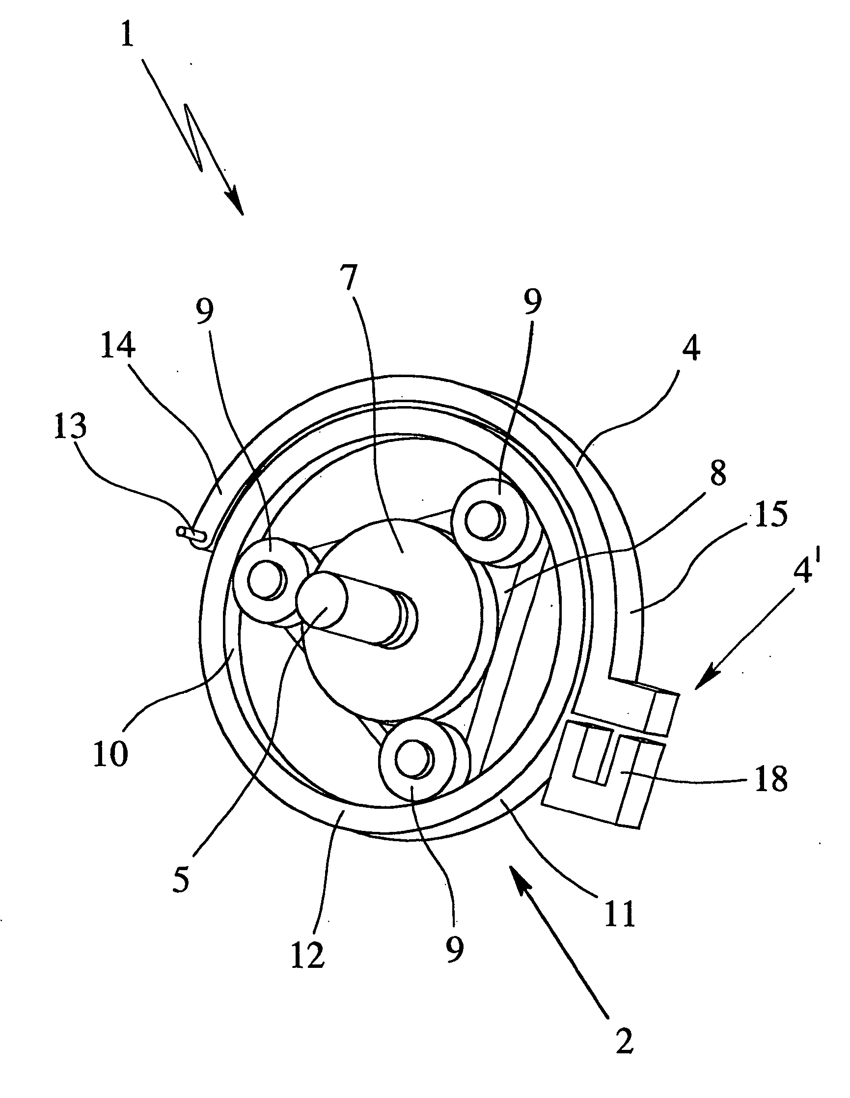
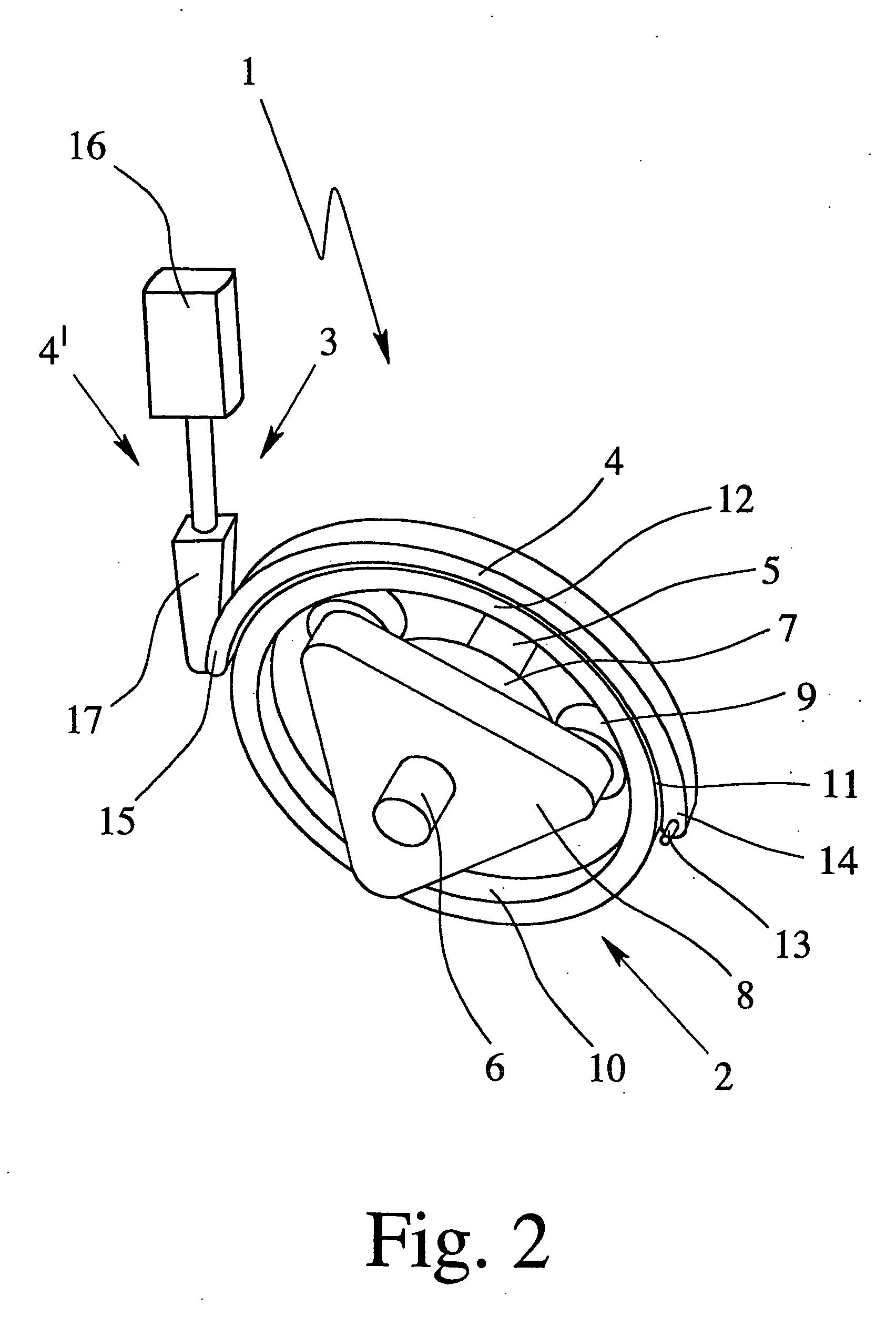
[0038] The drive device 1, as shown in FIG. 2, has a planet gear 2 and a brake device 3 with a brake 4. The planet gear 2 has a drive shaft 5, a driven shaft 6, a sun wheel 7, a planet carrier 8 with planet wheels 9, and a ring gear 10.

[0039] The drive shaft 5 can be driven by motor by a drive 5a w...


PUM


Abstract

A drive arrangement for a motor vehicle door or hatch which can be moved by a motor with a planet gear and a brake device with a brake. The brake device has a brake drive which is separate from the drive which drives the drive shaft and the brake is able to be moved at least from one of two positions into the other of the two positions by the brake drive. The brake can be an arc-shaped clip pivotally supported by a pivot axle with an inner periphery which is matched to an outer periphery of an element of the planet gear. The brake can be combined with the brake drive as an eddy current brake or can be operated by a further gearing or use of a permanent magnet with which an electromagnet is able to interact.

Description

BACKGROUND OF THE INVENTION [0001] 1. Field of Invention [0002] This invention relates to a drive arrangement for a motor vehicle door or hatch which can be moved by a motor with a planet gear and a brake device with a brake, the planet gear having a drive shaft, a driven shaft, a sun wheel, a planet carrier with planet wheels and a ring gear, the drive shaft being able to be driven by the motor and the driven shaft being coupled to the motor vehicle door or hatch. One of the elements which include the sun wheel, planet carrier and ring gear being coupled to the drive shaft, a second of the elements which include the sun wheel, planet carrier and ring gear being coupled to the driven shaft and the third of the elements which include the sun wheel, planet carrier and ring gear being able to be braked or blocked by means of the brake. The third of the elements which include the sun wheel, planet carrier and ring gear is not braked or blocked in the first position of the brake-released...

Claims


Application Information

Patent Timeline
Patent Type & Authority Applications(United States)
IPC IPC(8): E05F15/10E05F15/12E05F15/14F16D65/14F16H48/06
CPCE05Y2201/218E05F15/603E05Y2201/462E05Y2201/72E05Y2800/11E05Y2900/50E05Y2900/531F16D2121/20F16D2121/24F16D2129/065E05Y2201/21E05Y2201/236E05Y2201/68E05Y2400/854E05Y2400/86E05Y2900/546E05Y2201/246Y10T292/1079
Inventor GUELER, MEHMETKORTYRBA, SLAWOMIRHEINRICH, ANDREASBARTEL, PETERKAMBERG, AXEL
Owner BROSE SCHLIESSSYSTEME GMBH & CO KG
Why Eureka
Try Eureka