
SQUID magnetic sensor

a magnetic sensor and squid technology, applied in the direction of magnetic measurement, magnetic field measurement using superconductive devices, instruments, etc., can solve the problems of squid magnetic sensor long-time stability, sensitivity reduction, and performance degradation of squid magnetic sensor, so as to reduce the magnetic trapping in the squid ring area, small magnetic field measurement, and conduct stably

Inactive Publication Date: 2013-10-01
TOYOHASHI UNIVERSITY OF TECHNOLOGY
View PDF8 Cites 3 Cited by
  • Summary
  • Abstract
  • Description
  • Claims
  • Application Information

AI Technical Summary

Benefits of technology

This configuration allows for stable operation in small magnetic fields and improved sensitivity, enabling measurements in high magnetic noise environments without the need for magnetic shields, with enhanced magnetic flux linking and reduced noise levels.

Problems solved by technology

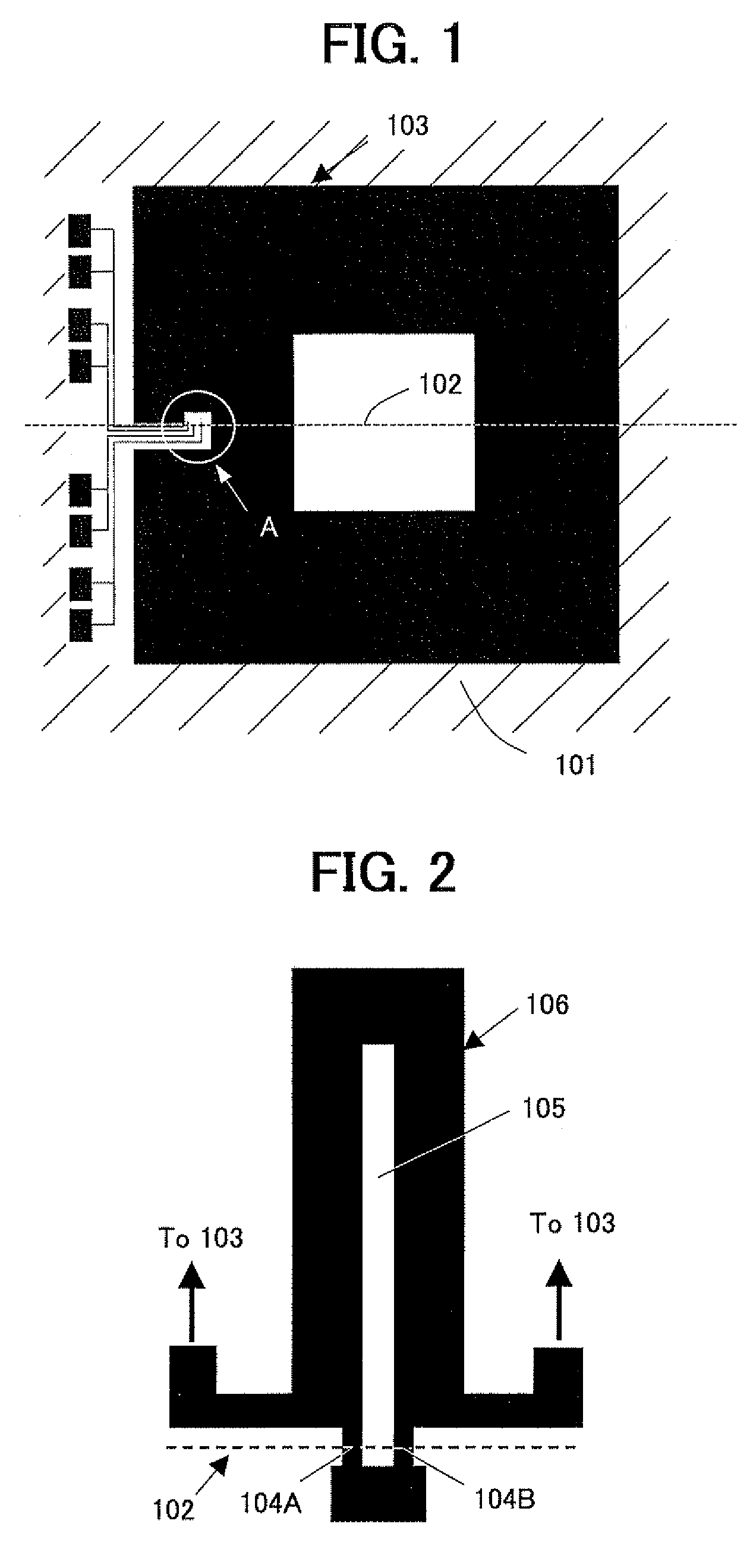
In particular, if the magnetic flux is trapped in the bi-crystal grain boundary junctions 104A, 104B of the SQUID ring 106, the performance of the SQUID magnetic sensor degrades and the sensitivity thereof is decreased, leading to the difficulty in the long-time stable operation of the SQUID magnetic sensor.
Therefore, the SQUID magnetic sensor in such a pattern has the lower magnetic field robustness, and thus it is difficult to use it in measurements conducted in an environment with high magnetic field noise or in the magnetic field.

Method used


Image

  • SQUID magnetic sensor
  • SQUID magnetic sensor
  • SQUID magnetic sensor

Examples


example 1

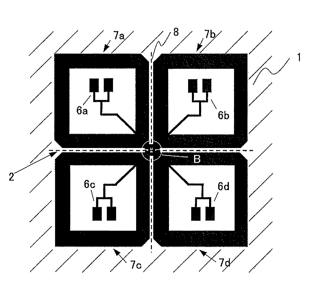
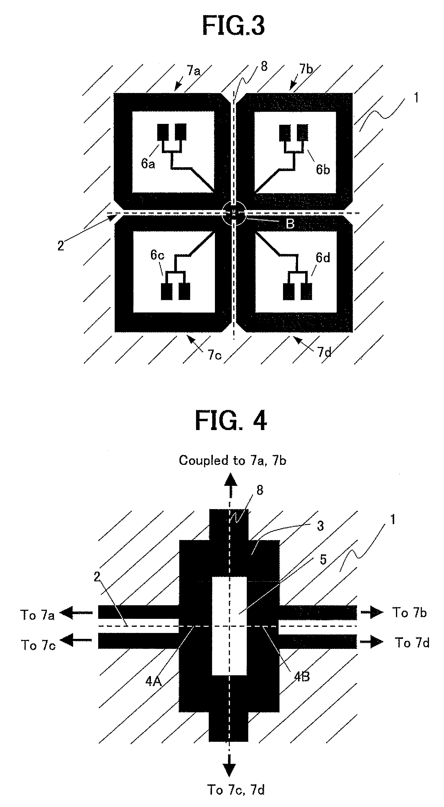
[0037]The performance of the SQUID magnetic sensor was experimentally verified for the directly-coupled high-temperature superconductor SQUID magnetic sensor in the single thin film structure, as shown in FIG. 3, fabricated to have the size of each pickup loop of 1.5 mm×1.5 mm and the bi-crystal Josephson junctions, that was cooled using liquid nitrogen (boiling point of 77K). The result showed that, when the 100 Hz magnetic field was applied, the SQUID operated stably up to the magnetic field of 0.75 μT.

example 2

[0039]The performance of the SQUID magnetic sensor was experimentally verified for the directly-coupled high-temperature superconductor SQUID magnetic sensor in the single thin film structure, as shown in FIG. 3, fabricated to have the size of each pickup loop of 1.5 mm×1.5 mm and the bi-crystal Josephson junctions, that was cooled using liquid nitrogen (boiling point of 77K), and for the sensor as shown in FIGS. 5 and 6, fabricated to have the flip-chip structure of the bi-crystal substrate 11 and the SQUID magnetic sensor.

[0040]Table 1 shows characteristics of the SQUID sensor with and without the superconducting thin film mounted thereon. For the SQUID magnetic sensor without the superconducting thin film, critical current, amplitude of external magnetic field at which the SQUID magnetic sensor becomes to operate unstably, effective flux trapping area, and a white flux noise level were 14 μA, 0.75 μT, 0.066 mm2, and 20 μφ0 / Hz1 / 2 respectively. On the other hand, for the same SQUID...


PUM


Abstract

There is provided a directly-coupled high-temperature superconductor SQUID magnetic sensor in a single thin film structure, which suppresses flux trapping or jumping generated in the sensor in a magnetic field, prevents the degradation in performance of the SQUID sensor, and operates stably with high sensitivity even in the magnetic field. The SQUID magnetic sensor including a bi-crystal substrate 1 having a bi-crystal grain boundary, pickup loops 7a-7d formed from a first high-temperature superconducting thin film on the bi-crystal substrate 1, and a SQUID ring 3 formed from the first high-temperature superconducting thin film on the bi-crystal grain boundary, directly connected with the pickup loops 7a-7d, wherein a plurality of pickup loops 7a-7d are disposed equally spaced from a bi-crystal grain boundary line 2 so as not to overlap with the bi-crystal grain boundary.

Description

BACKGROUND OF THE INVENTION[0001]1. Field of the Invention[0002]The present invention relates to a directly-coupled high-temperature superconductor SQUID (Superconducting QUantum Interference Device) magnetic sensor in a single thin film structure having high sensitivity, which operates stably even in the environmental magnetic noise without the use of a magnetic shield or the like.[0003]2. Description of the Related Art[0004]The high-temperature superconductor SQUIDs are adequately sensitive magnetic sensors. However, directly-coupled high-temperature superconductor SQUID magnetic sensors in a single thin film structure using bi-crystal grain boundary junctions produce flux trapping / jumping when subjected to a magnetic field of tens to hundreds of nT, resulting in the unstable operation (for example, see Non-Patent Document 1). As such, when using the high-temperature superconductor SQUID magnetic sensors in the magnetic field for measurements or using the sensors in an environment...

Claims


Application Information

Patent Timeline
Patent Type & Authority Patents(United States)
IPC IPC(8): G01R33/035H10N60/80
CPCG01R33/035
Inventor HATSUKADE, YOSHIMITANAKA, SABUROKANAI, SHO
Owner TOYOHASHI UNIVERSITY OF TECHNOLOGY
Learn More