Method for linking segments and linking tool

a technology of linking segments and linking tools, which is applied in the direction of manufacturing tools, shaft equipment, shaft linings, etc., can solve the problems of difficult operation of manual screwing motion, and achieve the effects of reducing labor intensity, reducing labor intensity, and reducing labor intensity

Active Publication Date: 2010-04-29
SHONAN GOSEI JUSHI SEISAKUSHO KK
View PDF7 Cites 2 Cited by
  • Summary
  • Abstract
  • Description
  • Claims
  • Application Information

AI Technical Summary

Benefits of technology

[0011]According to the present invention, a linking pin, which is inserted into the insertion hole of the side plate of a segment, is separated into pin halves by a separating pin. The pin halves are pressed against the segment, thereby anchoring the linking pin to the segment. The other end of the linking pin outside the segment is snap-fitted into another segment, allowing the two segments to be linked in the longitudinal direction of the rehabilitating pipe. Screw-fastening is therefore unnecessary, and the segments can be assembled in confined spaces where a manual screwing motion is difficult to perform. The assembly operation can be simplified and shortened even during assembly in open spaces. Excellent effects are obtained in that construction time is shortened, the burden on workers is lightened, and the number of workers required is reduced even during a construction work for assembling a rehabilitating pipe using the segments to repair an existing pipeline.

Problems solved by technology

Screw-fastening is therefore unnecessary, and the segments can be assembled in confined spaces where a manual screwing motion is difficult to perform.

Method used


Image

  • Method for linking segments and linking tool
  • Method for linking segments and linking tool
  • Method for linking segments and linking tool

Examples


Embodiment Construction

[0035]The present invention will be described in detail hereinafter on the basis of the embodiments shown in the accompanying drawings.

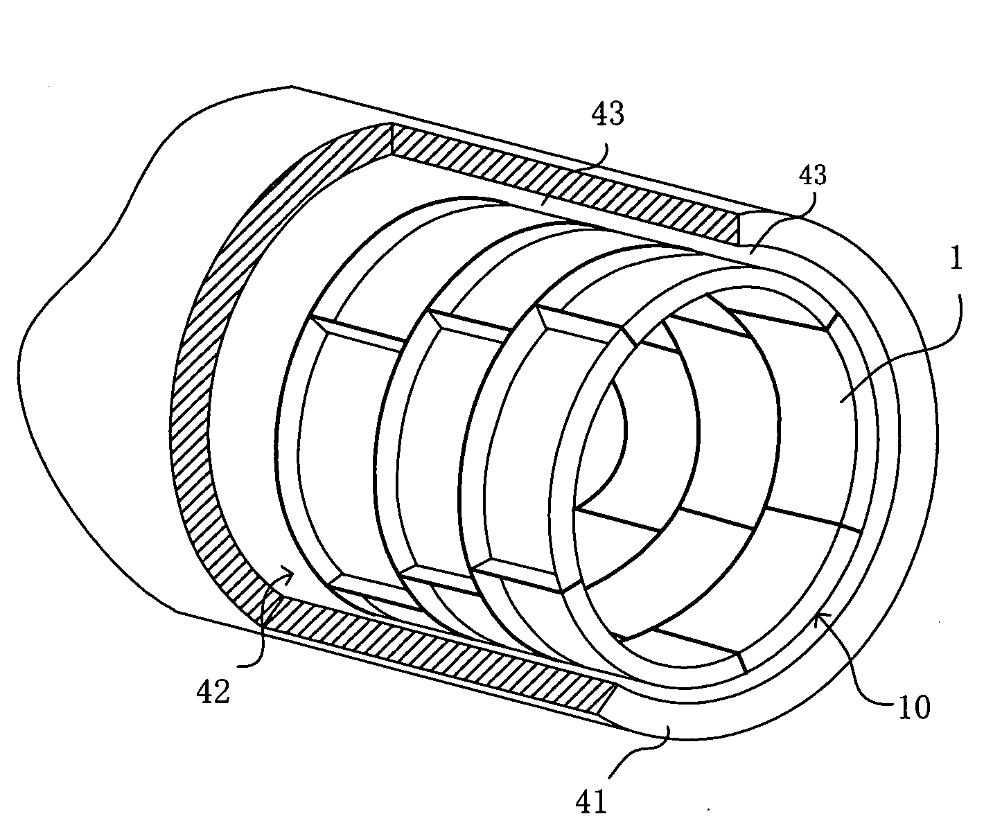
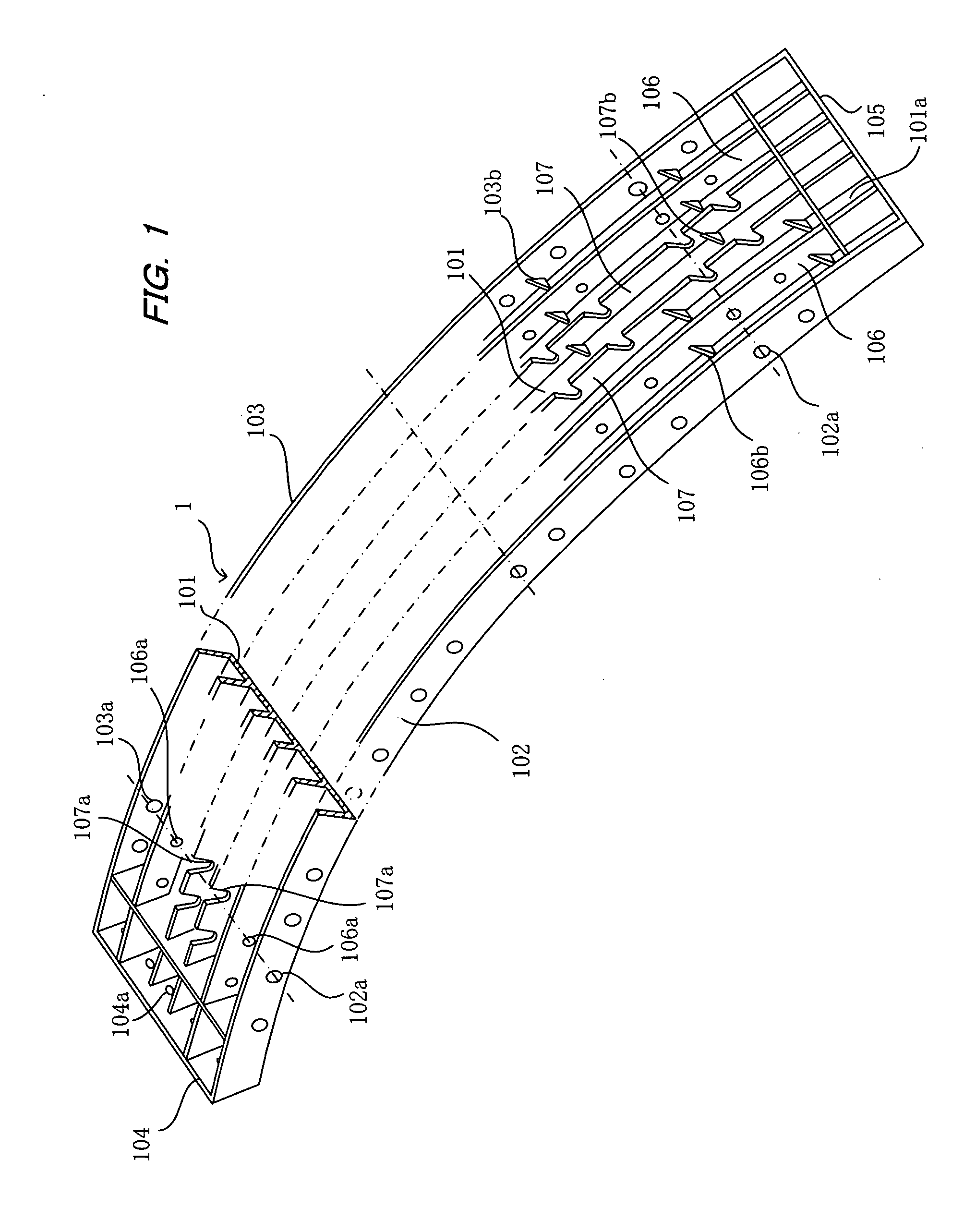
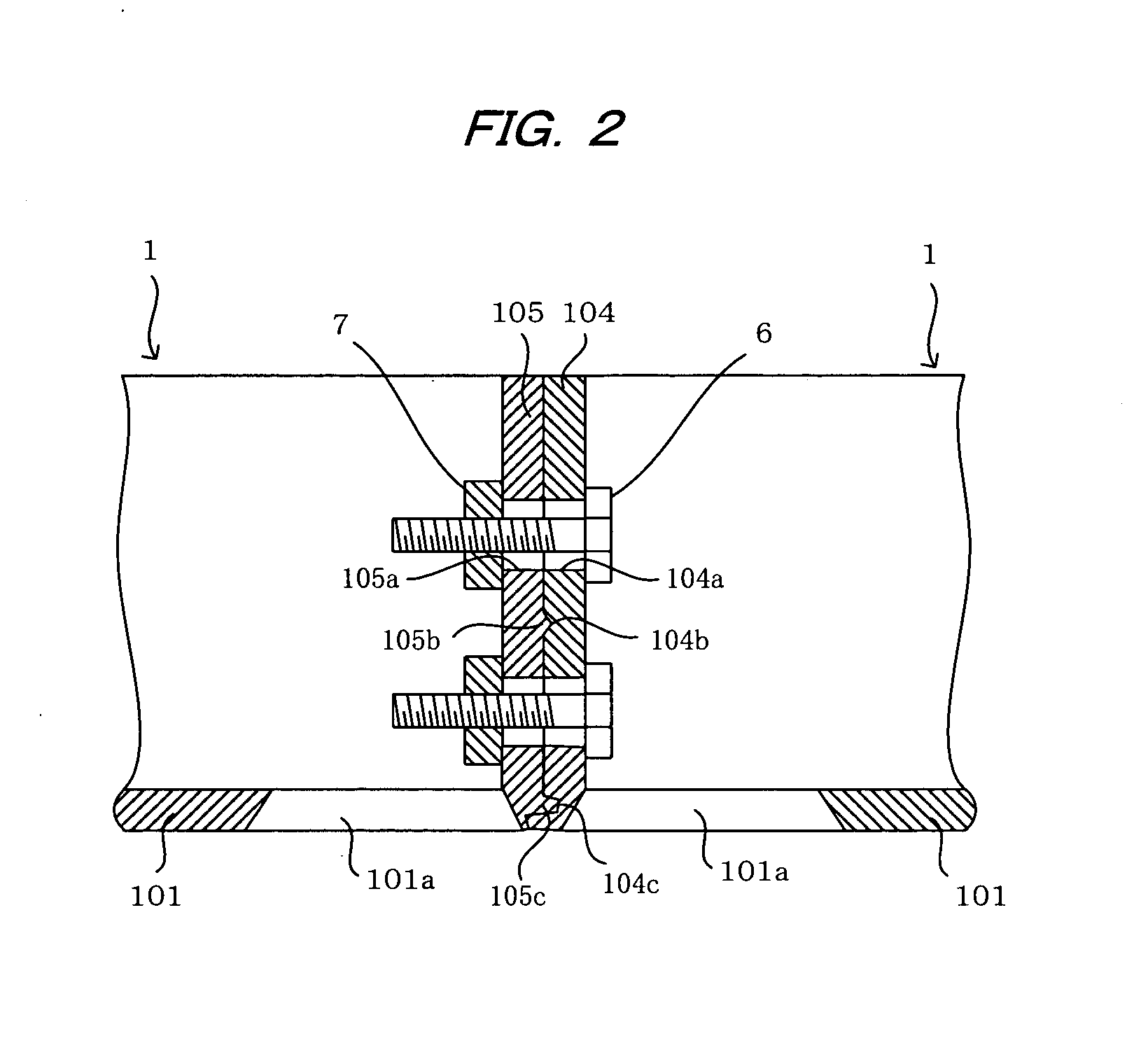
[0036]FIG. 1 shows a segment 1 that serves as an assembly unit for a pipe for rehabilitating an existing pipe such as a sewerage pipe, a waterworks pipe, an agricultural water pipe and the like. The segment 1 is a block-shaped member that is integrally formed of plastic from an internal surface plate 101 that constitutes an inner circumferential surface of the rehabilitating pipe; side plates 102, 103 that are vertically disposed at both sides of the internal surface plate 101 so as to extend in the circumferential direction of the rehabilitating pipe; and end plates 104, 105 that are vertically disposed at both ends of the internal surface plate 101 so as to extend in the longitudinal direction of the pipe. The side plates 102, 103 and the end plates 104, 105 of the segment 1 have the same height and form an outer-wall plate that surrounds the rim o...


PUM

PropertyMeasurementUnit
widthaaaaaaaaaa
diameteraaaaaaaaaa
thicknessaaaaaaaaaa

Abstract

A linking tool links segments for a rehabilitating pipe for rehabilitating an existing pipeline. The segment is integrally formed at least from an internal surface plate that constitutes the inner circumferential surface of the rehabilitating pipe, and side plates that have an insertion hole formed thereon and are disposed on both sides of the internal surface plate so as to extend in the circumferential direction of the rehabilitating pipe. The linking tool includes a tubular linking pin that is separable into pin halves and can be inserted into the insertion hole in the side plate of a first segment with a part of the linking pin remaining outside the first segment. The linking tool further includes a separating pin that can be inserted into the linking pin to separate the linking pin into the pin halves and press them against the first segment for anchoring thereto. The pin halves remaining outside the first segment are snap-fitted into a second segment through the insertion hole of the side plate thereof, thereby linking the first and second segments in the longitudinal direction of the rehabilitating pipe. Such a linking tool allows the segments to be efficiently linked in a short period of time

Description

BACKGROUND OF THE INVENTION[0001]1. Field of the Invention[0002]The present invention relates to a method for linking segments and a linking tool, and more particularly to a method for linking segments that are used as an assembly unit of a pipe for rehabilitating existing pipes or pipelines, and to a linking tool used in this method.[0003]2. Description of the Related Art[0004]In cases where sewage pipes or other pipelines that are buried underground have aged, methods for constructing a pipe lining have already been proposed and are being employed in practical applications.[0005]With the aforementioned methods for constructing a pipe lining, a pipe-lining material, which is formed, e.g., by impregnating a tubular resin-adsorbent material with an uncured thermosetting resin, is inserted into a pipeline via fluid pressure while being everted, and the impregnated thermosetting resin is cured by heating the pipe-lining material in the state where the pipe-lining material is pressed ag...

Claims


Application Information

Patent Timeline
Patent Type & Authority Applications(United States)
IPC IPC(8): F16L55/163B23P11/00
CPCF16B5/065F16L9/22Y10T29/49954F16L55/165F16L55/1657F16L11/18E03F7/00F16L55/00F16L55/162F16L58/02
Inventor KAMIYAMA, TAKAOKANETA, KOJIFUJII, KENJIMIURA, KATSUYORI
Owner SHONAN GOSEI JUSHI SEISAKUSHO KK
Why Eureka
Try Eureka