Device for the treatment of femoral fractures

a technology for femoral fractures and devices, applied in the field of devices for the treatment of femoral fractures, can solve the problems of time-consuming adjustment for surgeons, the screw cannot rotate in the sleeves, and the hip screw moves medially, so as to prevent excessive medial movement, reduce the damage to the bony substance, and prevent the effect of excessive rotation

Active Publication Date: 2010-12-14
SYNTHES USA
View PDF27 Cites 46 Cited by
  • Summary
  • Abstract
  • Description
  • Claims
  • Application Information

AI Technical Summary

Benefits of technology

[0011]due to the rotatability of the sliding sleeve on the shaft of the bone fixing element, the introduction of the sliding sleeve after the implanting of the bone fixing element is possible prior to the assembly without long adjustment of the sliding sleeve and consequently the operation will be simplified and shortened;
[0023]The locking means are preferably so dimensioned, that they act as an axial stop with regard to the passage of the intramedullary pin. This stop prevents excessive medial movement of the bone fixing element.

Problems solved by technology

The shaft of the hip screw and the bore of the sleeve are, however, not circular, so that the hip screw cannot rotate in the sleeve.
However, during the introduction into the head of the femur the hip screw has to be able to rotate.
There is further the danger that the hip screw moves medially when a compression screw is not additionally employed.
A further disadvantage is, that the locking screw has to be introduced from above (cranially) into the intramedullary pin, representing a further operating procedure.
This known device has the disadvantage that the prior introduced hip screw has to be rotated again one way or another during the assembly of the sliding sleeve, until it is so aligned that the non-circular cross-sections of the shaft, the external and internal profiles of the sliding sleeve and of the passage allow the introduction of the sliding sleeve.
This means a time-consuming adjustment for the surgeon.
A further disadvantage of this device is that a medial movement can be prevented only with an additional component (tension adjuster).

Method used


Image

  • Device for the treatment of femoral fractures
  • Device for the treatment of femoral fractures
  • Device for the treatment of femoral fractures

Examples


Embodiment Construction

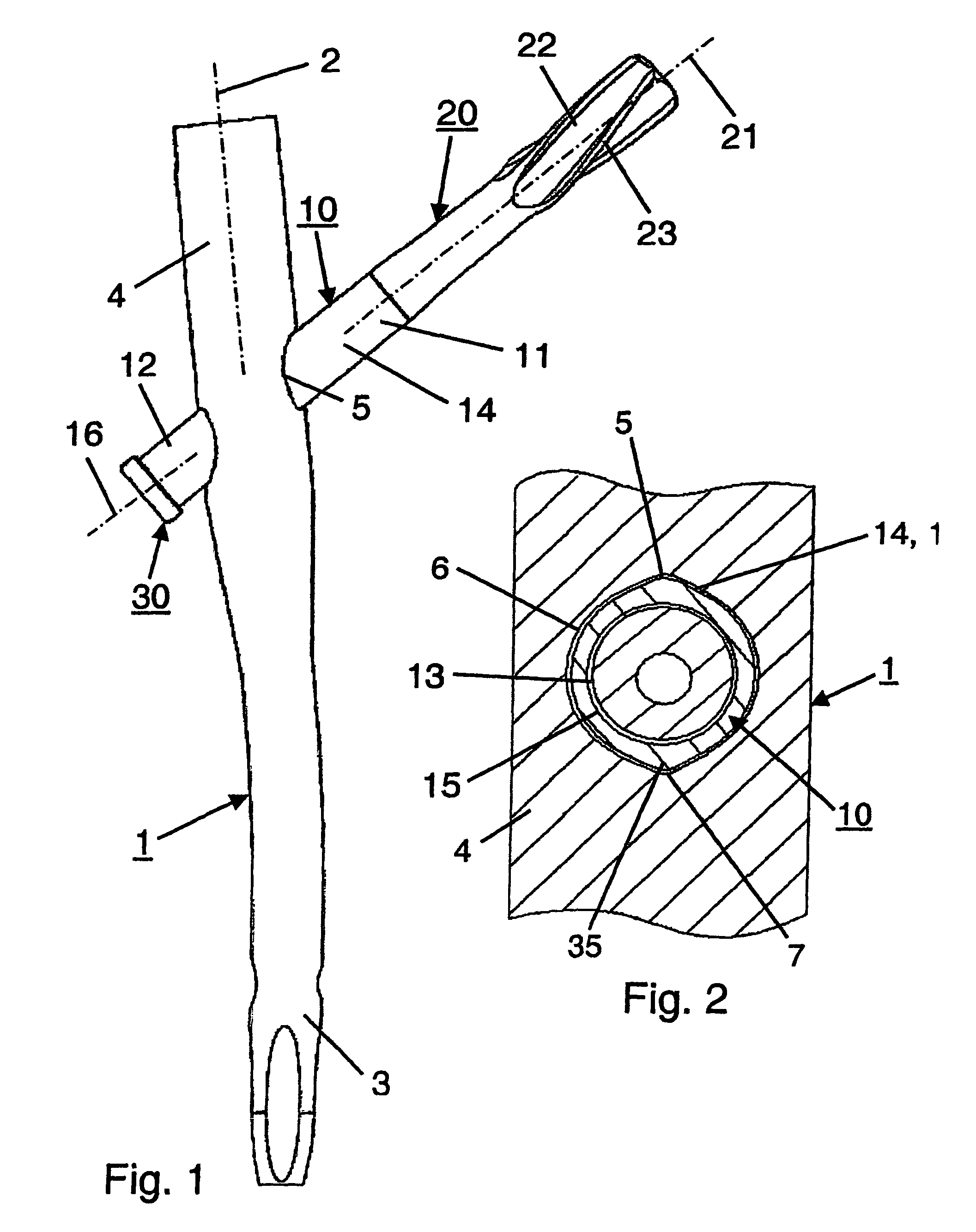
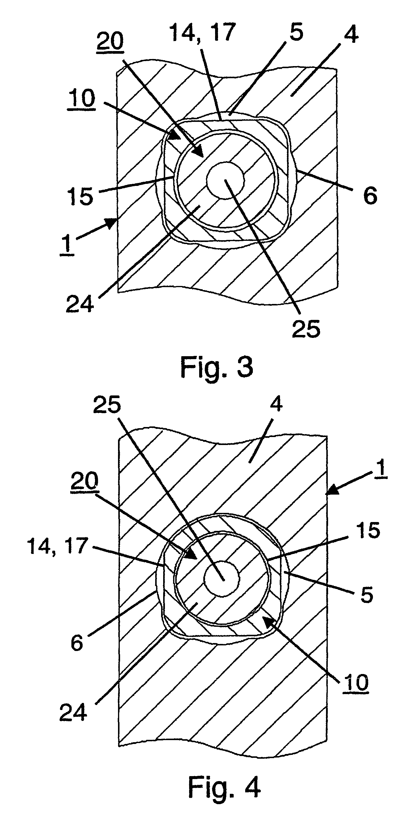
[0041]In FIGS. 1-2, as well as FIGS. 5-8, a device for the treatment of femoral fractures is illustrated, that comprises an intramedullary pin 1, a sliding sleeve 10, a longitudinal bone fixing element 20 in the form of a hip screw or a helical blade, and a locking means 30. The intramedullary pin 1 has a central longitudinal axis 2, a front portion 3 that can be introduced into the medullary canal, a rear portion 4, as well as a passage 5 with a non-circular cross-section 6 (FIGS. 2-4) that passes through the rear portion 4 obliquely to the longitudinal axis 2. The sliding sleeve 10, that can pass through the non-circular passage 5, has a front end 11, a rear end 12, a central longitudinal bore 13, an external jacket surface 14, an internal jacket surface 15, as well as a longitudinal axis 16.

[0042]The longitudinal bone fixing element 20, in the form of a hip screw or helical blade, has a longitudinal axis 21, a head portion 22 with fixing means 23 in the form of a multi-start thre...


PUM


Abstract

A femoral fracture treatment device including: an intramedullary pin (1) with a central longitudinal axis (2) and a passage (5) of non-circular cross-section (6) through a proximal portion (4) of the pin oblique to the longitudinal axis (2), a sliding sleeve (10) configured to pass through the non-circular passage (5), a longitudinal bone fixing element (20) having a head portion (22) with fixing means (23) for engaging the femoral head and a shaft (24) that may be coaxially introduced into the sliding sleeve (10). Both an external jacket surface (14) of the sliding sleeve (10) and an internal jacket surface (15) of the sliding sleeve (10) have non-circular cross-sections at least in a partial section. The shaft (24) is rotatably mounted in the longitudinal bore (13) of the sliding sleeve (10), and locking means are provided at the free end (27) of the shaft (24), such that rotation of the longitudinal bone fixing element (20) relative to the sliding sleeve (10) can be optionally locked or released.

Description

RELATED APPLICATION DATA[0001]The present application is a continuation of, and claims priority under 35 U.S.C. §120 to, International Application No. PCT / CH2003 / 000630, filed Sep. 18, 2003, the entire content of which is expressly incorporated herein by reference thereto.FIELD OF INVENTION[0002]The invention concerns a device for the treatment of femoral fractures.BACKGROUND OF THE INVENTION[0003]Devices, whereby a securing of the femoral head against rotation is attempted by a single hip screw, i.e. a longitudinal bone fixing means, are already known. From EP 0 441 577, for example, a device is known that has a sleeve accommodating the hip screw in a sliding manner, while the sleeve can be secured against rotation in the intramedullary pin by a locking screw proximally introduced into the intramedullary pin. The shaft of the hip screw and the bore of the sleeve are, however, not circular, so that the hip screw cannot rotate in the sleeve. However, during the introduction into the ...

Claims


Application Information

Patent Timeline
Patent Type & Authority Patents(United States)
IPC IPC(8): A61B17/76A61B17/78
CPCA61B17/744A61B17/74
Inventor FRIGG, ROBERTHATTLER, ERICWIDMER, WALTERBARRIOS, ELENAKUPPERS, STEPHAN
Owner SYNTHES USA
Why Eureka
Try Eureka