

Helmet providing cervical spine protection
- Summary
- Abstract
- Description
- Claims
- Application Information
AI Technical Summary
Benefits of technology
Problems solved by technology
Method used
Image


Examples
Embodiment Construction
[0037]While this invention is susceptible of embodiment in many different forms, there are shown in the drawings and will be described in details herein two specific embodiments, with the understanding that the present disclosure is to be considered as an example of the principles of the invention and is not intended to limit the invention to the embodiments illustrated and described.
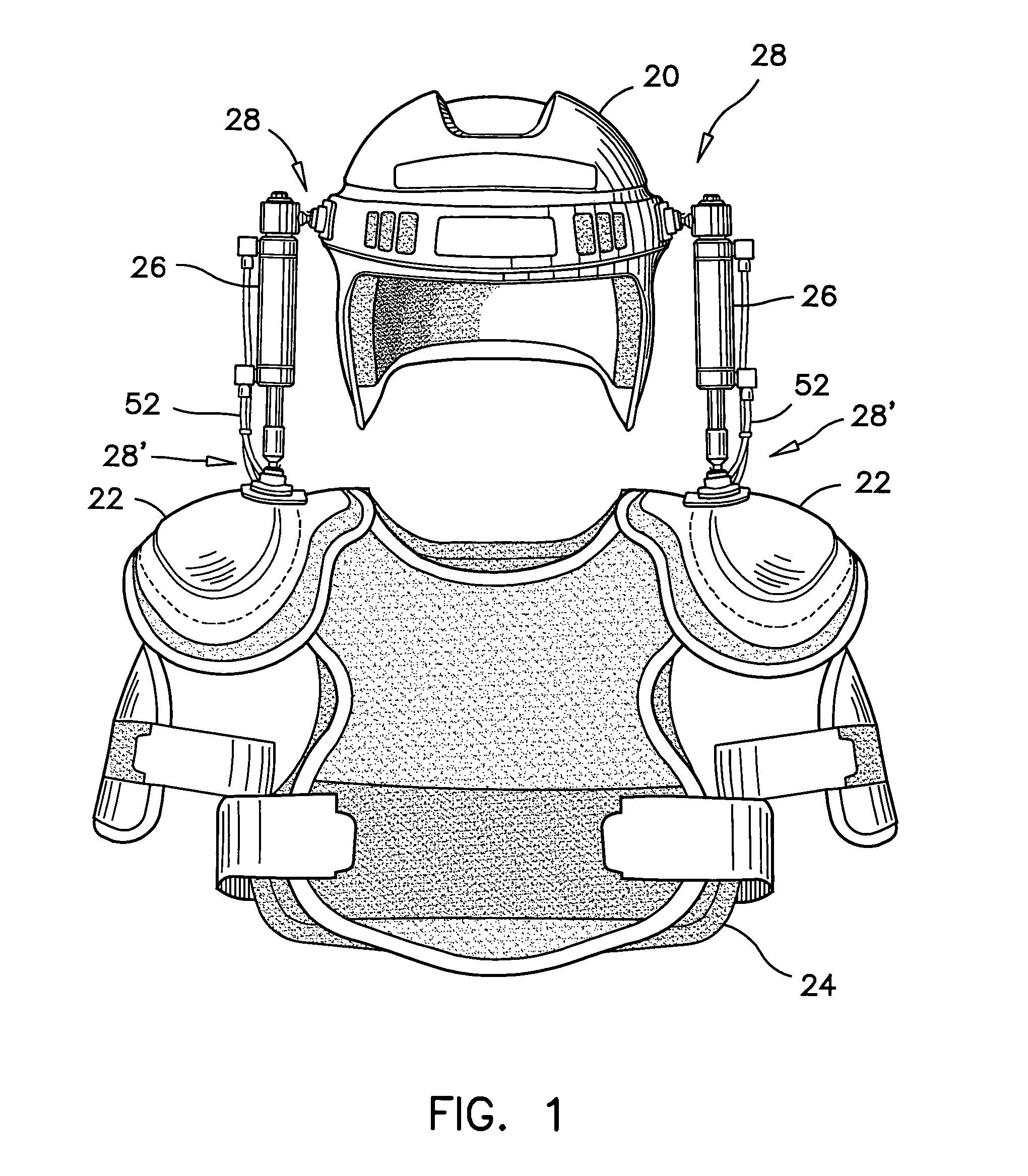
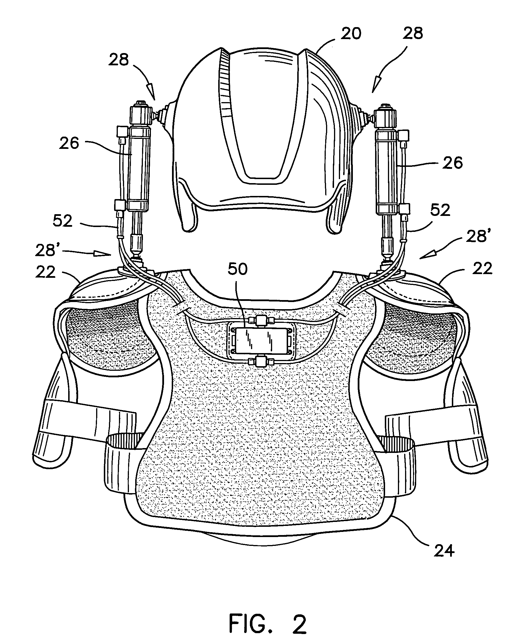
[0038]Referring firstly to FIGS. 1, 2 and 3 simultaneously, the protective sport equipment according to the first preferred embodiment will be described. The protective sport equipment comprises a helmet 20 and a set of shoulder pads 22 mounted to a protective vest 24. A pair of hydraulic cylinders 26 extend between the helmet 20 and the shoulder pads 22. The shoulder pads 22 are retained to the protective vest 24 as it is customary with hockey equipment.
[0039]The hydraulic cylinders 26 are affixed to the helmet 20 and to the shoulder pads 22 by means of ball and socket joints 28, 28′ each having a deta...
PUM
 Abstract
Description
Claims
Application Information