Audio decoding device, decoding method, and program

a decoding method and audio technology, applied in the field of audio decoding apparatus and decoding method for decoding a coded audio signal, can solve the problems of large deterioration of sound quality level, and general muffled reproduction sound, so as to reduce calculation and apparatus scale, reduce the required amount of calculations, and improve sound quality level

Active Publication Date: 2009-06-30
PANASONIC CORP +1
View PDF14 Cites 121 Cited by
  • Summary
  • Abstract
  • Description
  • Claims
  • Application Information

AI Technical Summary

Benefits of technology

[0023]It is an object of the present invention to provide a band expansion technique for maintaining high sound quality and reducing an amount of calculations required, and an audio decoding apparatus, an audio decoding method, and an audio decoding program which employ such a band expansion technique.
[0032]In another audio decoding apparatus according to the present invention, the corrective coefficient extractor may calculate the signal phase of the low-frequency subband signals and may calculate the energy corrective coefficient based on the signal phase. Alternatively, the corrective coefficient extractor may calculate the ratio of the energy of a real part of the low-frequency subband signals and the signal energy of the low-frequency subband signals as the energy corrective coefficient. Further alternatively, the corrective coefficient extractor may average the phases of samples of the low-frequency subband signals to calculate the energy corrective coefficient. Still further alternatively, the corrective coefficient extractor may smooth energy corrective coefficients calculated respectively in the frequency bands.
[0042]The audio decoding apparatus according to the present invention resides in that it has an energy corrector for correcting a target energy for high-frequency components and a corrective coefficient calculator for calculating an energy corrective coefficient from low-frequency subband signals or a corrective coefficient generator for generating an energy corrective coefficient according to a predetermined process. These processors perform a process for correcting a target energy that is required when a band expanding process is performed on a real number only. Thus, a real subband combining filter and a real band expander which require a smaller amount of calculations can be used instead of a complex subband combining filter and a complex band expander, while maintaining a high sound-quality level, and the required amount of calculations and the apparatus scale can be reduced. If the corrective coefficient generator for generating an energy corrective coefficient without using low-frequency subband signals is employed, then a real subband dividing filter which requires a small amount of calculations can be used in addition to the subband combining filter and the band expander, further reducing the required amount of calculations and the apparatus scale.

Problems solved by technology

However, since the high-frequency components are not coded, the sound-quality level is deteriorated, and the reproduced sound is generally of muffled nature.
The conventional audio decoder has been problematic in that it has a subband divider and a complex subband combiner which require a large amount of calculations, and the required amount of calculations and the apparatus scale are large because the band expansion process is carried out using complex numbers.

Method used


Image

  • Audio decoding device, decoding method, and program
  • Audio decoding device, decoding method, and program
  • Audio decoding device, decoding method, and program

Examples


1st embodiment

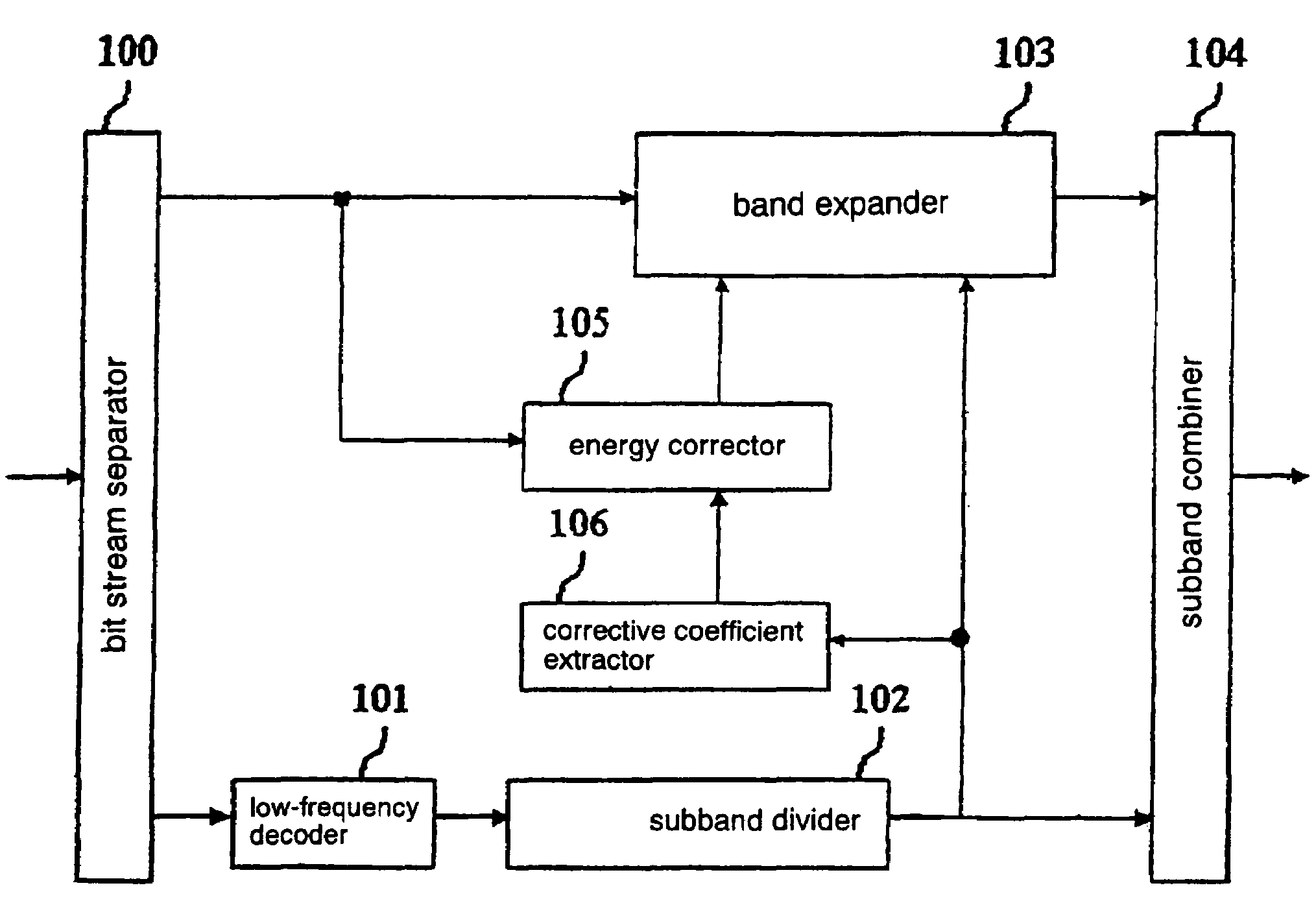
[0052]FIG. 6 is a block diagram of an audio decoding apparatus according to a first embodiment of the present invention. The audio decoding apparatus according to the present embodiment comprises bit stream separator 100, low-frequency decoder 101, subband divider 102, band expander 103, subband combiner 104, energy corrector 105, and corrective coefficient extractor 106.

[0053]Bit stream separator 100 separates an input bit stream and outputs separated bit streams to low-frequency decoder 101, band expander 103, and energy corrector 105. Specifically, the input bit stream comprises a multiplexed combination of a low-frequency bit stream representing a low-frequency signal that has been coded and a high-frequency bit stream including information that is required for band expander 103 to generate a high-frequency signal. The low-frequency bit stream is output to low-frequency decoder 101, and the high-frequency bit stream is output to band expander 103 and energy corrector 105.

[0054]L...

2nd embodiment

[0084]A second embodiment of the present invention will be described in detail below with reference to FIG. 7.

[0085]FIG. 7 shows an audio decoding apparatus according to the second embodiment of the present invention. The audio decoding apparatus according to the present embodiment comprises bit stream separator 100, low-frequency decoder 101, subband divider 202, band expander 103, subband combiner 104, corrective coefficient generator 206, and energy corrector 105.

[0086]The second embodiment of the present invention differs from the first embodiment of the present invention in that subband divider 102 is replaced with subband divider 202, and corrective coefficient extractor 106 is replaced with corrective coefficient generator 206, and is exactly identical to the first embodiment as to the other components. Subband divider 202 and corrective coefficient generator 206 will be described in detail below.

[0087]Subband divider 202 has a subband dividing filter that divides the input l...


PUM


Abstract

An energy corrector (105) for correcting a target energy for high-frequency components and a corrective coefficient calculator (106) for calculating an energy corrective coefficient from low-frequency subband signals are newly provided. These processors perform a process for correcting a target energy that is required when a band expanding process is performed on a real number only. Thus, a real subband combining filter and a real band expander which require a smaller amount of calculations can be used instead of a complex subband combining filter and a complex band expander, while maintaining a high sound-quality level, and the required amount of calculations and the apparatus scale can be reduced.

Description

TECHNICAL FIELD[0001]The present invention relates to an audio decoding apparatus and decoding method for decoding a coded audio signal.BACKGROUND ART[0002]MPEG-2 AAC (Advanced Audio Coding) which is an international standard process of ISO / IEC is widely known as an audio coding / decoding process for coding an audio signal with high sound quality at a low bit rate. According to conventional audio coding / decoding processes that are typified by the MPEG-2 AAC, a plurality of samples from a time-domain PCM signal are put together into a frame, which is converted into a frequency-domain signal by a mapping transform such as MDCT (Modified Discrete Cosine Transform). The frequency-domain signal is then quantized and subjected to Huffman coding to produce a bit stream. For quantizing the frequency-domain signal, in view of the hearing characteristics of the human being, the quantizing accuracy is increased for more perceptible frequency components of the frequency-domain signal and reduced...

Claims


Application Information

Patent Timeline
Patent Type & Authority Patents(United States)
IPC IPC(8): G10L19/00H03M7/30
CPCG10L21/038G10L19/032H03M7/30
Inventor NOMURA, TOSHIYUKISHIMADA, OSAMUTAKAMIZAWA, YUICHIROSERIZAWA, MASAHIROTANAKA, NAOYATSUSHIMA, MINEONORIMATSU, TAKESHICHONG, KOK SENGKUAH, KIM HANNNEO, SUA HONG
Owner PANASONIC CORP
Why Eureka
Try Eureka