Method of evaluating a readout signal, and optical disc apparatus
a technology of optical discs and readout signals, applied in the direction of digital signal error detection/correction, amplitude demodulation, instruments, etc., can solve the problems of generating errors, inability to evaluate a data pattern consisting of spaces and marks with a minimum run-length,
- Summary
- Abstract
- Description
- Claims
- Application Information
AI Technical Summary
Benefits of technology
Problems solved by technology
Method used
Image
Examples
embodiment 1
Handling of a Variety of PR Classes
[0136] In the foregoing descriptions, methods of calculating S-SEAT and V-SEAT with respect to a PR(1,2,2,1) decoder adapted to the RLL(1,7) code. In the following, an embodiment is described that relates to the PR(1,2,1), PR(12221), and PR(123321) classes adapted to the RLL(1,7) code, and the PR(3,4,4,3) class adapted to the RLL(2,10) code.
[0137] Initially, the PR class adapted to the RLL(1,7) code, such as for Blu-ray Disc, will be discussed.
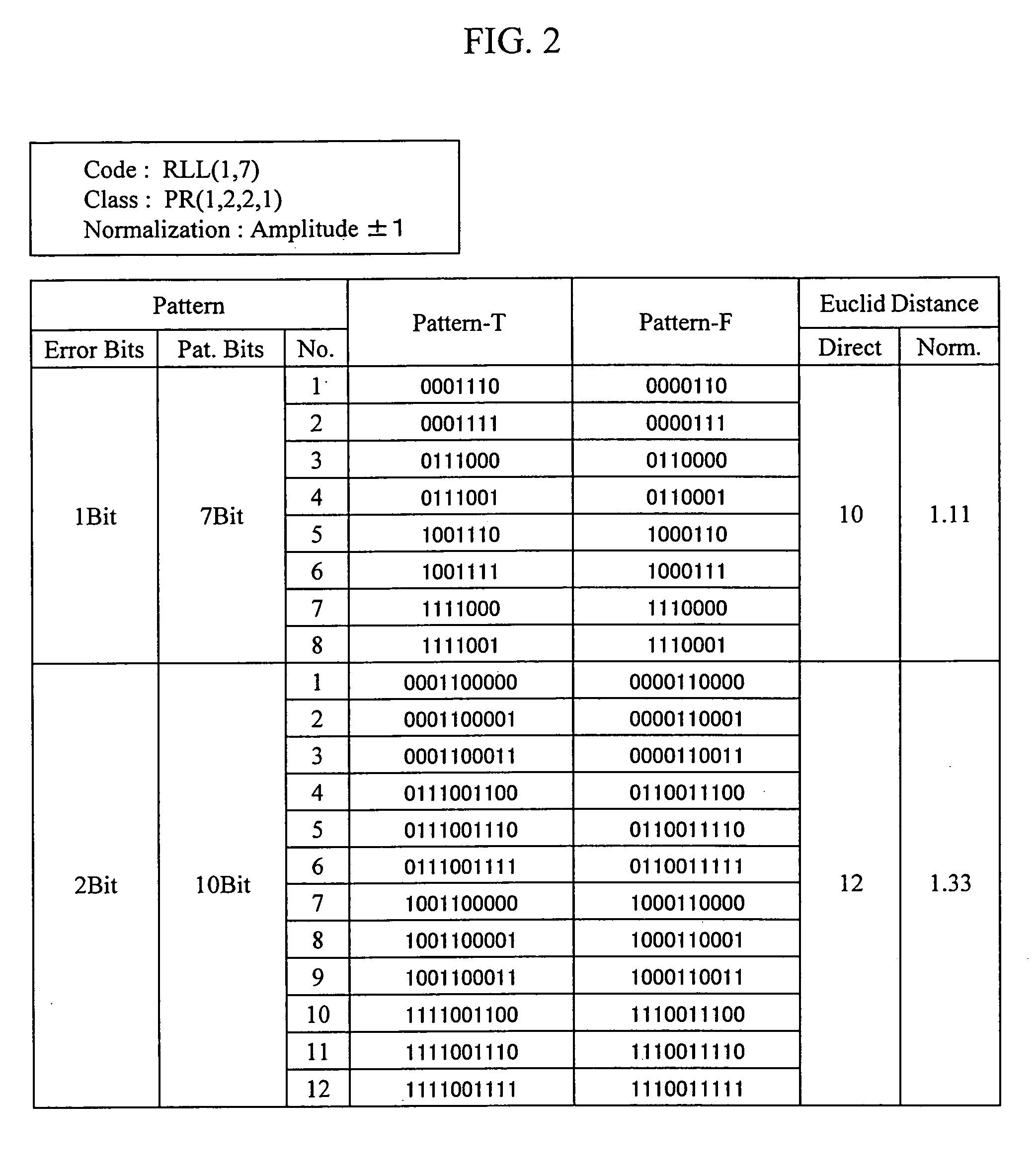
[0138]FIG. 12 shows a summary of the Euclidean distance and the edge shift direction for 1-bit error patterns for the PR(1,2,1) and PR(a,b,c) classes adapted to the RLL(1,7) code. As shown in the drawing, there are two combinations of patterns for the 1-bit error, and the Euclidean distance for a fixed target level is 6. The definition of the edge shift direction for each pattern is as shown.
[0139] First, the calculation of S-SEAT will be described.
[0140]FIG. 13 shows a summary of the target signal level...
embodiment 2
Circuit Configuration
[0182] Hereafter, the configuration of an example of a circuit suitable for the calculation of S-SEAT and V-SEAT is described with reference to the drawings.
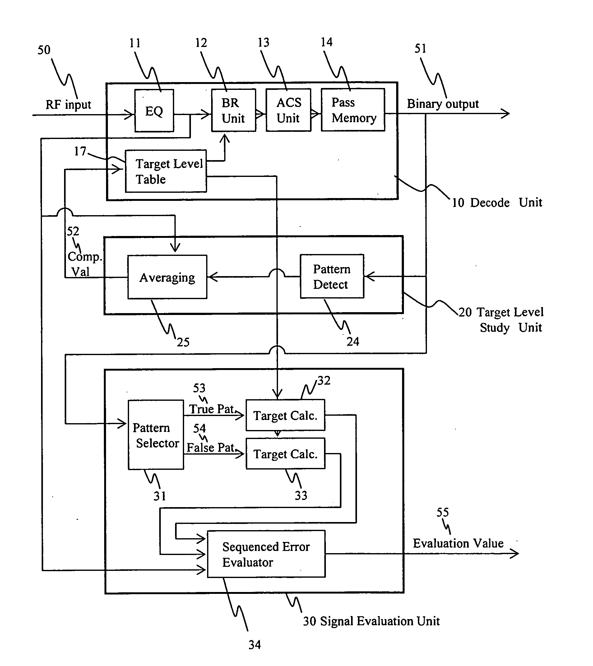
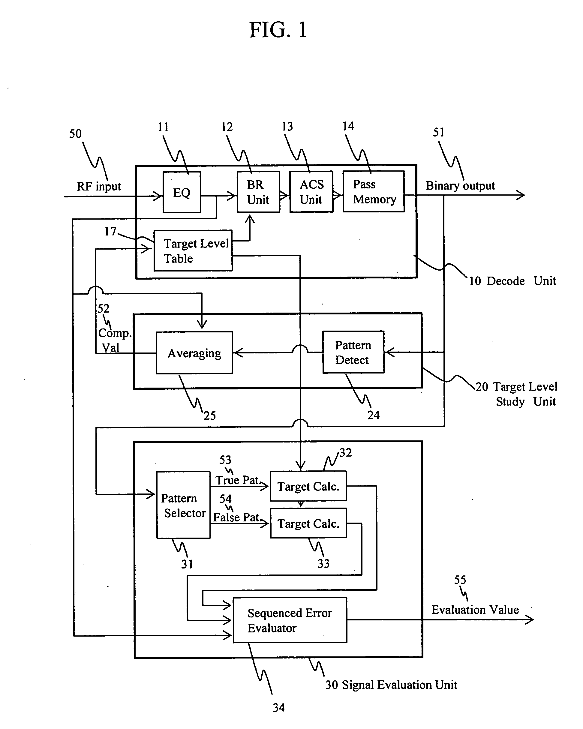
[0183]FIG. 1 shows the configuration of an S-SEAT calculation circuit mounted on an optical disc apparatus of the invention. The circuit consists of a decoding unit 10, a target level studying unit 20, and a signal evaluation unit 30.
[0184] Initially, the decoding unit 10 is described. The decoding unit 10 includes a waveform equalizer 11, a branch metric calculation unit 12, an ACS (Add Select Compare) unit 13, a path memory 14, and a target level table 17. A read signal 50, which is converted into a digital value in advance by an AD converter, is equalized by an FIR filter in the waveform equalizer 11. The read signal 50 is then fed to the branch metric calculation unit 12, where the square of the error from a target value (“branch metric value”) is calculated for each bit sequence. For the target value...
embodiment 3
Cases where Branch Metric Calculation is Carried out using Absolute Values
[0232] As mentioned above, in a Viterbi decoder, in order to obtain a most feasible binarization result, a branch metric value is used that is obtained by adding up the square of the difference between read signal and target signal. Such a Viterbi decoder will be hereafter referred to as the squared system. The squared value Δ2 of the difference between read signal and target level is as follows: Δ2=(Vsignal[t]-Vtarget[n])2=(Vsignal[t])2-2Vsignal[t]Vtarget[n]+(Vtarget[n])2(Eq. A-1)
where Vsignal[t] is the level of read signal at time t, and Vtarget[n] is a target signal level corresponding to a bit sequence n. In the Viterbi decoder, binarization is carried out such that the Δ2 accumulated value becomes minimum. The first term on the right hand side indicates the level of read signal, which is common to all bit sequences and therefore does not need to be calculated. In the case of a Viterbi decode...
PUM
 Abstract
Description
Claims
Application Information
 - R&D
- Intellectual Property
- Life Sciences
- Materials
- Tech Scout
- Unparalleled Data Quality
- Higher Quality Content
- 60% Fewer Hallucinations
Browse by: Latest US Patents, China's latest patents, Technical Efficacy Thesaurus, Application Domain, Technology Topic, Popular Technical Reports.
© 2025 PatSnap. All rights reserved.Legal|Privacy policy|Modern Slavery Act Transparency Statement|Sitemap|About US| Contact US: help@patsnap.com


