Arrays of optical confinements and uses thereof

Active Publication Date: 2006-03-23
PACIFIC BIOSCIENCES
View PDF84 Cites 128 Cited by
  • Summary
  • Abstract
  • Description
  • Claims
  • Application Information

AI Technical Summary

Benefits of technology

[0013] In addition, the invention provides a method of sequencing a plurality of target nucleic acid molecules. The method typically involves (a) providing an array of optical confinements having a density on a substrate exceeding 4×10⁴ confinements per mm2, or any other density described herein or equivalents thereof, wherein said optical confinements provide an effective observation volume that permits observation of individual molecules; and an optical system operatively coupled to the optical confinements that detects signals from the effective observation volume of said confinement; (b) mixing in the optical confinements the plurality of target nucleic acid molecules, primers complementary to the target nucleic acid molecules, polymerization enzymes, and more than one type of nucleotides or nucleotide analogs to be incorporated into a plurality of nascent nucleotide strands, each strand being complementary to a respective target nucleic acid molecule; (c) subjecting the mixture of step (b) to a polymerization reaction under conditions suitable for formation of the nascent nucleotide strands by template-directed polymerization of the nucleotides or nucleotide analogs; (d) illuminating the optical confinements with an incident light beam; and (e) identifying the nucleotides or the nucleotide analogs incorporated into the each nascent nucleotide strand.
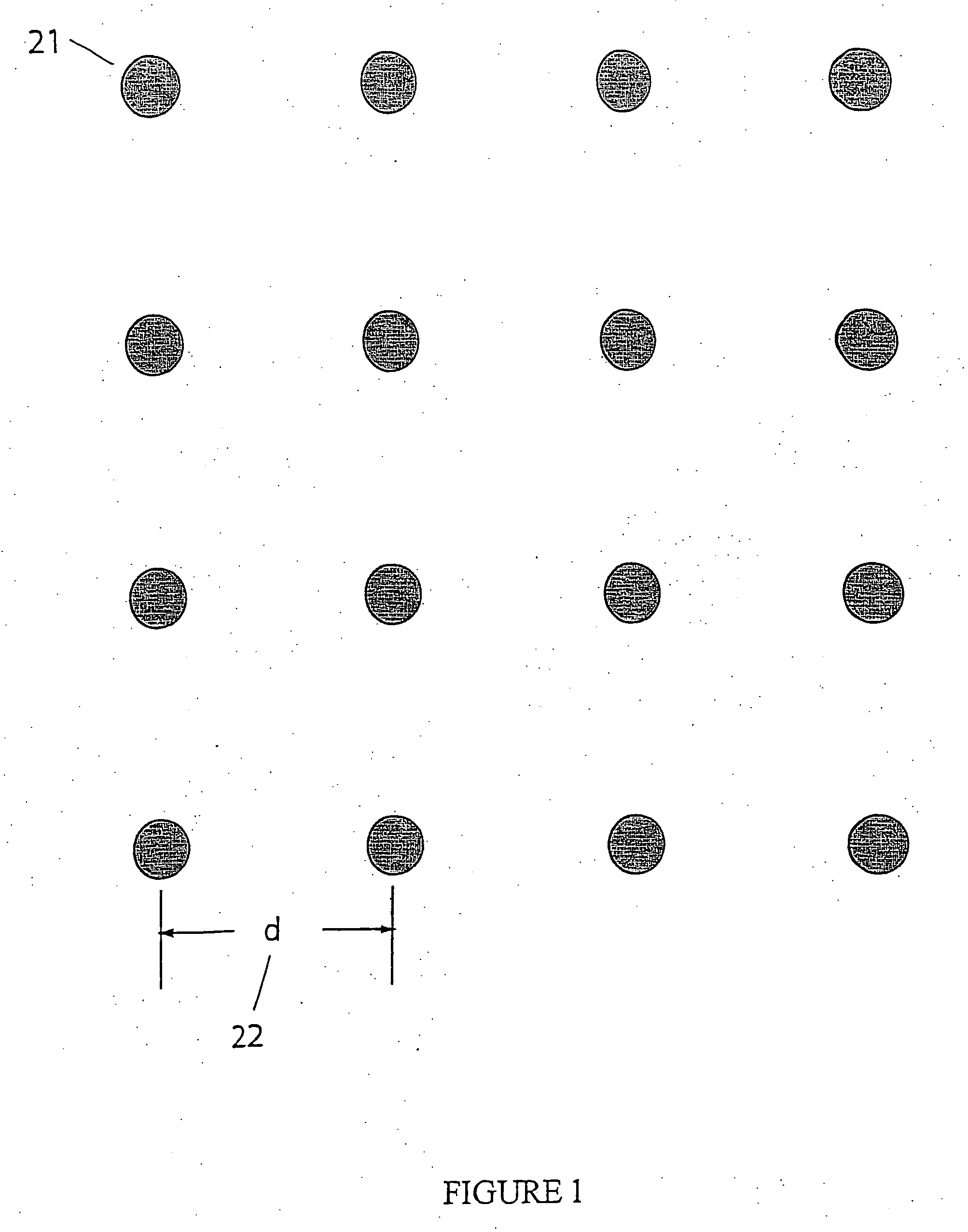
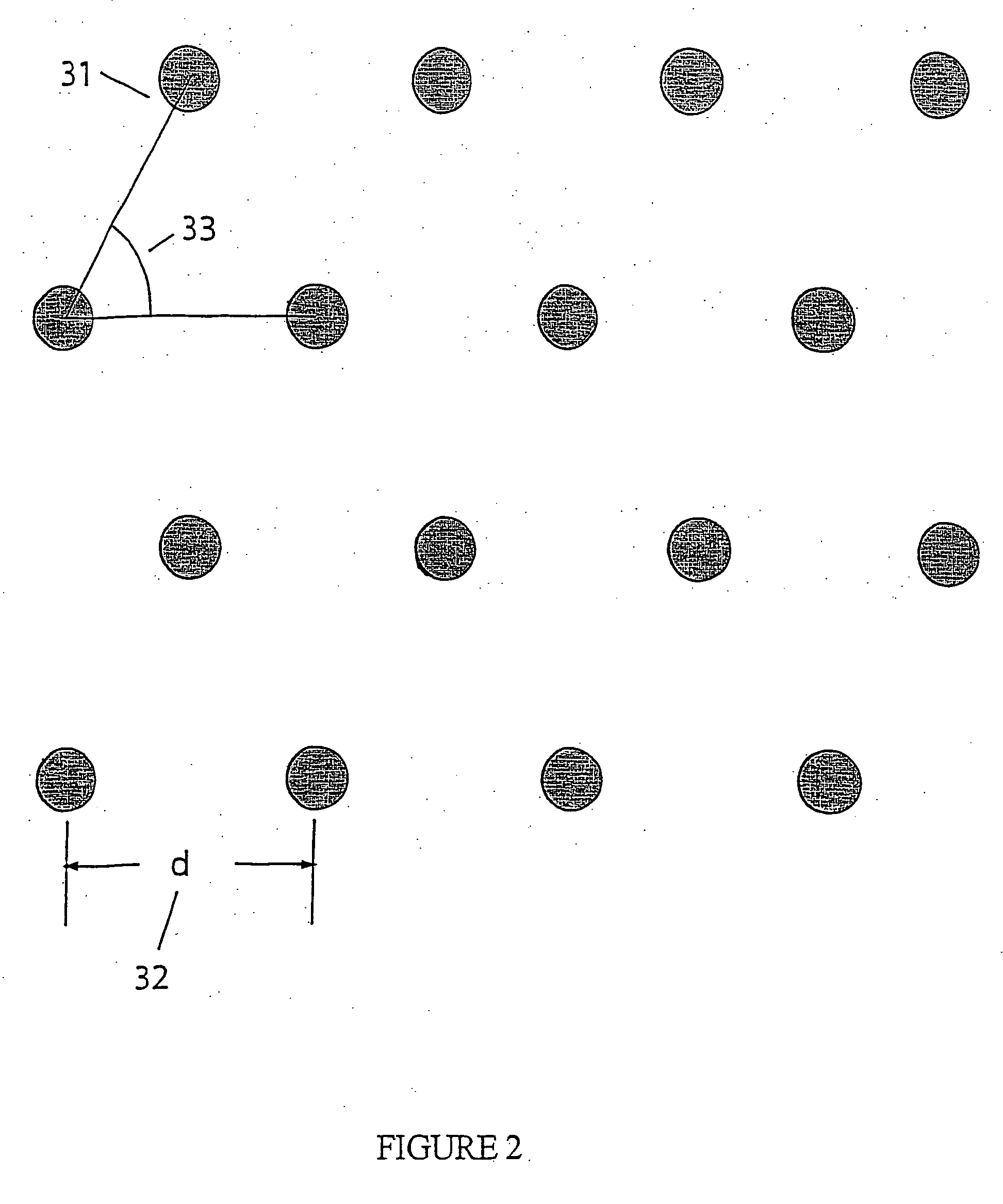
[0014] The present invention also provides an apparatus comprising an array of waveguides on a solid support having a fill fraction greater than about 0.0001, wherein said waveguides are suitable for holding a biological reagent, and wherein waveguides provide an effective observation volume that permits observation of individual molecules present in said biological reagent; and an optical system that detects said individual molecules in said waveguides, by e.g., detecting signals from the effective observation volume. In one aspect, the array has a fill fraction greater than about 0.001. In another aspect, the array has a fill fraction greater than about 0.01, in some instances greater than 0. 1, or within the range about 0.001 to about 0.1.
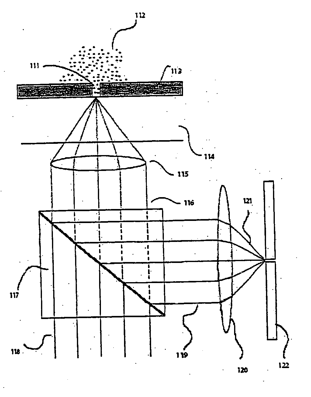
[0015] The present invention also provides various methods of using such high fill fraction array. In one embodiment, the present invention provides a method of detecting a biological analyte. The method comprises optically capturing the analyte within an optical confinement that

Problems solved by technology

The array of optical confinements may further comprise another array of confinements that does not yield

Method used


Image

  • Arrays of optical confinements and uses thereof
  • Arrays of optical confinements and uses thereof
  • Arrays of optical confinements and uses thereof

Examples


example 1

[0206] The following provides an illustrative process of fabricating zero-mode waveguide. The parameters described herein are meant to be illustrative and not intended to be limiting in any manner. [0207] 1. Substrates: Substrates are double polished, 60 / 40 scratch / dig surface quality, Fused Silica wafers, cut to 100 millimeters(±0.2 mm) diameter, and 175 micrometer(±25 micrometers) thick and a total thickness variation of less than 25 micrometers. [0208] 2. Clean: A mix of 5 parts deionized water, 1 part of (30% v / v Hydrogen Peroxide in water), 1 part of (30% v / v Ammonium Hydroxide in water) is heated to 75 degree Celsius on a hotplate. The wafers are immersed in the mix using a Teflon holder or other chemically resistant holder for a duration of 15 minutes. [0209] 3. Rinsing: The holder containing the wafers is removed from the RCA clean bath and immersed in a bath of deionized water. The wafers are left in this second bath for a 2 minutes period. The holder still containing the w...

example 2

Monitoring Enzymatic Synthesis of a DNA Strand by a Single DNA Polymerase Molecule in Real Time

[0238] This experiment can be performed using the optical system and reaction mixtures detailed below.

[0239] However, the reference to any particular optical system and parameter, buffer, reagent, concentration, pH, temperature, or the like, is not intended to be limiting. They are included to provide as one illustrative example of carrying out the methods of the present invention.

[0240] Enzymatic synthesis of a DNA strand by a single DNA polymerase molecule was tracked in real time using a fluorescently labeled nucleotides. Individual Phi29N62D DNA polymerase enzymes (Amersham Biosciences, Piscataway, N.J.) were immobilized in zero-mode waveguides (ZMWs) by non-specific binding using a dilute enzyme solution. After immobilization, the ZMW structures were washed to remove unbound enzyme, and then exposed to a solution containing the reaction reagents. As of the DNA template, a 70-bp pr...

example 3

Real Sequencing using Multiple Different Labeled Nucleotides

[0246] An experiment similar to that described in Example 2, above, was performed using two different labeled nucleotide analogs. The experiment can be performed using the optical setup or system and reaction mixtures detailed as follows. However, the reference to any particular optical setup and parameter, buffer, reagent, concentration, pH, temperature, or the like, is not intended to be limiting. They are included to provide as one illustrative example of carrying out the methods of the present invention.

[0247] Preparing reaction samples: Approximately 10 μl of reaction mixture is used in one sequencing reaction. The reaction mixture generally contains 0.5-1 mM MnCl2, 0.1-1 uM DNA template, 10 μM dATP, 10 μM dGTP, 10 μM SAP-treated Alexa 488-dC4P, and 10 μM SAP-treated Alexa 568-dT4P, and DNA polymerase. The labeled dC4P and dT4P can also be substituted with labeled dA4P and dG4P.

[0248] Preparing Zero-mode waveguide:...


PUM

PropertyMeasurementUnit
Fractionaaaaaaaaaa
Fractionaaaaaaaaaa
Molar densityaaaaaaaaaa

Abstract

The present invention relates to optical confinements, methods of preparing and methods of using them for analyzing molecules and/or monitoring chemical reactions. The apparatus and methods embodied in the present invention are particularly useful for high-throughput and low-cost single-molecular analysis.

Description

CROSS REFERENCE TO RELATED APPLICATION [0001] This application is a continuation-in-part of U.S. utility patent application Ser. No. 10 / 944,106, filed Sep. 17, 2004, pending, which is hereby incorporated herein by reference in its entirety for all purposes. This application also claims priority to U.S. Provisional Application Nos. 60 / 649,009 and 60 / 651,846 filed on Jan. 31, 2005 and Feb. 9, 2005, respectively, both of which are incorporated herein by reference for all purposes.BACKGROUND OF THE INVENTION [0002] Confinement of illumination and signal detection has long been recognized as an important tool in molecular diagnostics since the application of Fluorescence Correlation Spectroscopy (FCS). FCS involves illumination of a sample volume containing fluorophore-labeled molecules, and detection of fluctuations in fluorescence signal produced by the molecules as they diffuse into and out of an effective observation volume. The fluorescence intensity fluctuations can best be analyze...

Claims


Application Information

Patent Timeline
IPC IPC(8): G01N1/00
CPCB01L3/5085B01L2200/0668B01L2300/0654B01L2300/0896Y10T436/10B82Y30/00G01N21/6452G02B6/13B82Y20/00C12Q1/6869C12Q2521/101C12Q2521/543C12Q2561/113C12Q2565/537G01N35/028
Inventor TURNER, STEPHENKORLACH, JONAS
Owner PACIFIC BIOSCIENCES
Why Eureka
Try Eureka