
Automated package shipping machine

a package and automatic technology, applied in the field of commercial shipping and delivering industry, can solve the problems of not providing full insurance protection or verification of packages, present-day unattended drop-boxes cannot accept packages, and are generally inaccessible to customers, so as to achieve efficient utilization of the volume of storage area

Inactive Publication Date: 2008-06-05
RAMSDEN GARY W +1
View PDF58 Cites 23 Cited by
  • Summary
  • Abstract
  • Description
  • Claims
  • Application Information

AI Technical Summary

Benefits of technology

[0009]Accordingly, it is an object of this invention to provide a system which can accept and store items for subsequent pick-up by a commercial carrier.
[0021]a scale for weighing a parcel which a customer intends to ship; an input device for inputting information relating to the destination of the parcel from the customer; a control system for calculating a shipment fee for the parcel, the control system being in communication with the scale and the information inputting system; a secure deposit system, enabled by the control system, for permitting a customer to securely deposit the parcel into the storage area; and a stacking system in the storage area for stacking the parcel in the storage area, whereby the volume of the storage area will be efficiently utilized.

Problems solved by technology

Such schemes, however, cannot provide full insurance protection or verification that the package was in fact mailed, since no attendant is present to verify that the letter was actually placed in the box.
In addition, present-day unattended drop-boxes cannot accept packages because packages need to be pre-weighed and sized before they can be accepted for shipment.
Another disadvantage of unattended drop-boxes is that they are generally inaccessible to customers who do not have a pre-assigned customer account or specialized mailing envelope.
Such systems are also necessarily limited in the size and shape of items that they will accept for shipment.
Such offices can generally be used by persons who do not have a special account number with the company, but are usually limited in the hours of operation.
Such offices have a relatively high overhead cost for the company that operates them; this limits the number of such offices that a company can maintain.
As a result, many persons and companies seeking overnight or other expedited delivery service must either drive to the nearest office, which might be many miles away, or, if feasible, use a drop-box which does not give a verified deposit receipt.

Method used


Image

  • Automated package shipping machine
  • Automated package shipping machine
  • Automated package shipping machine

Examples


first embodiment

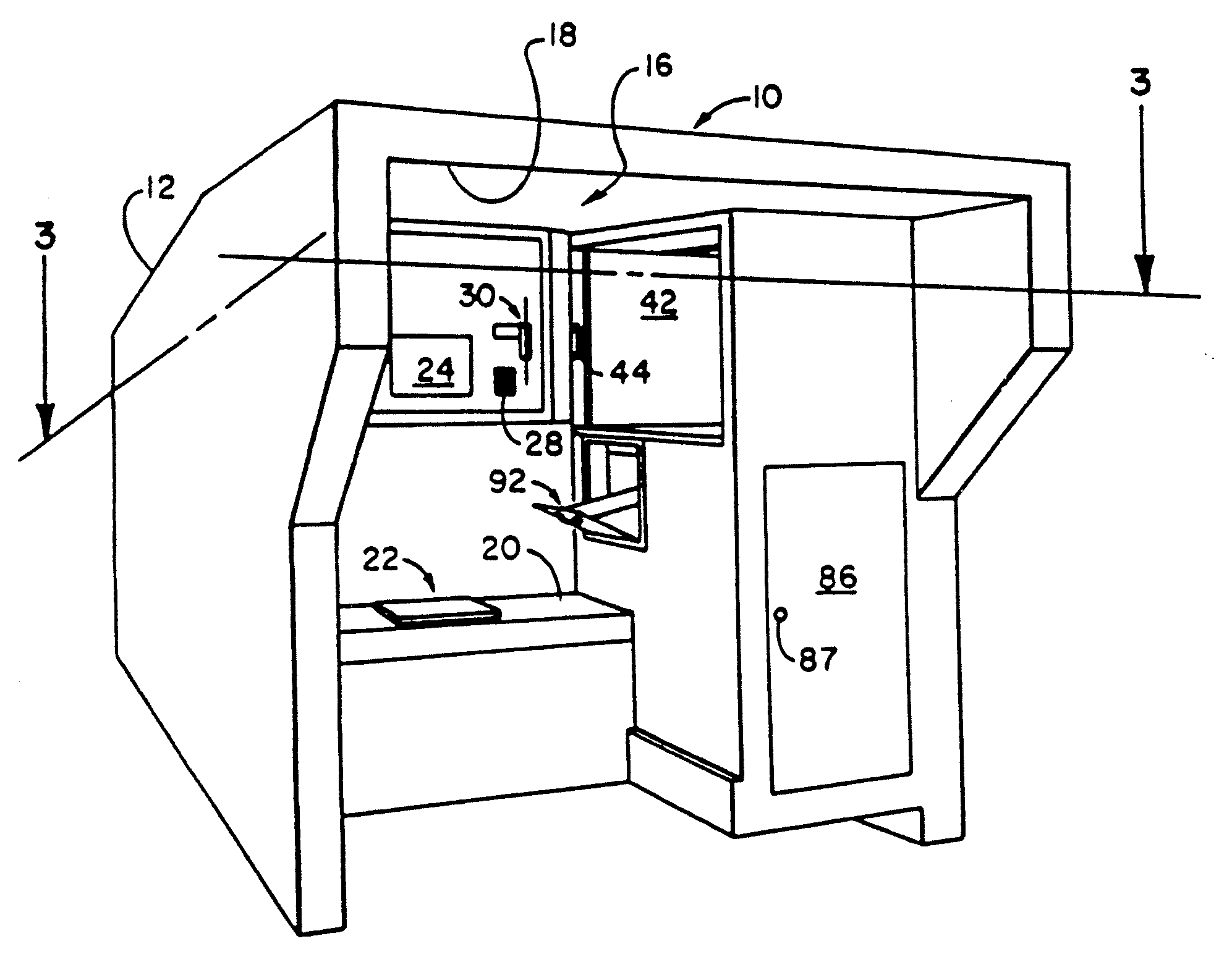
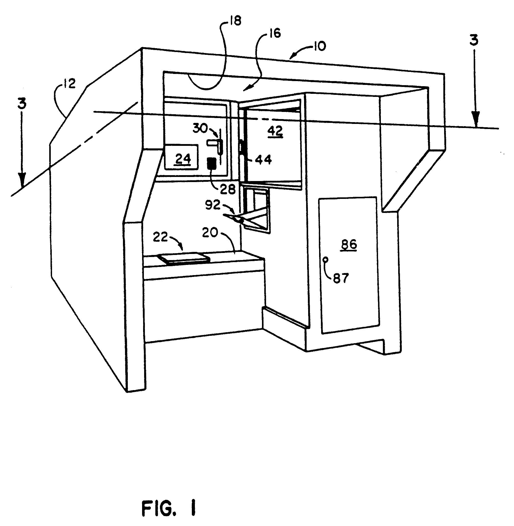
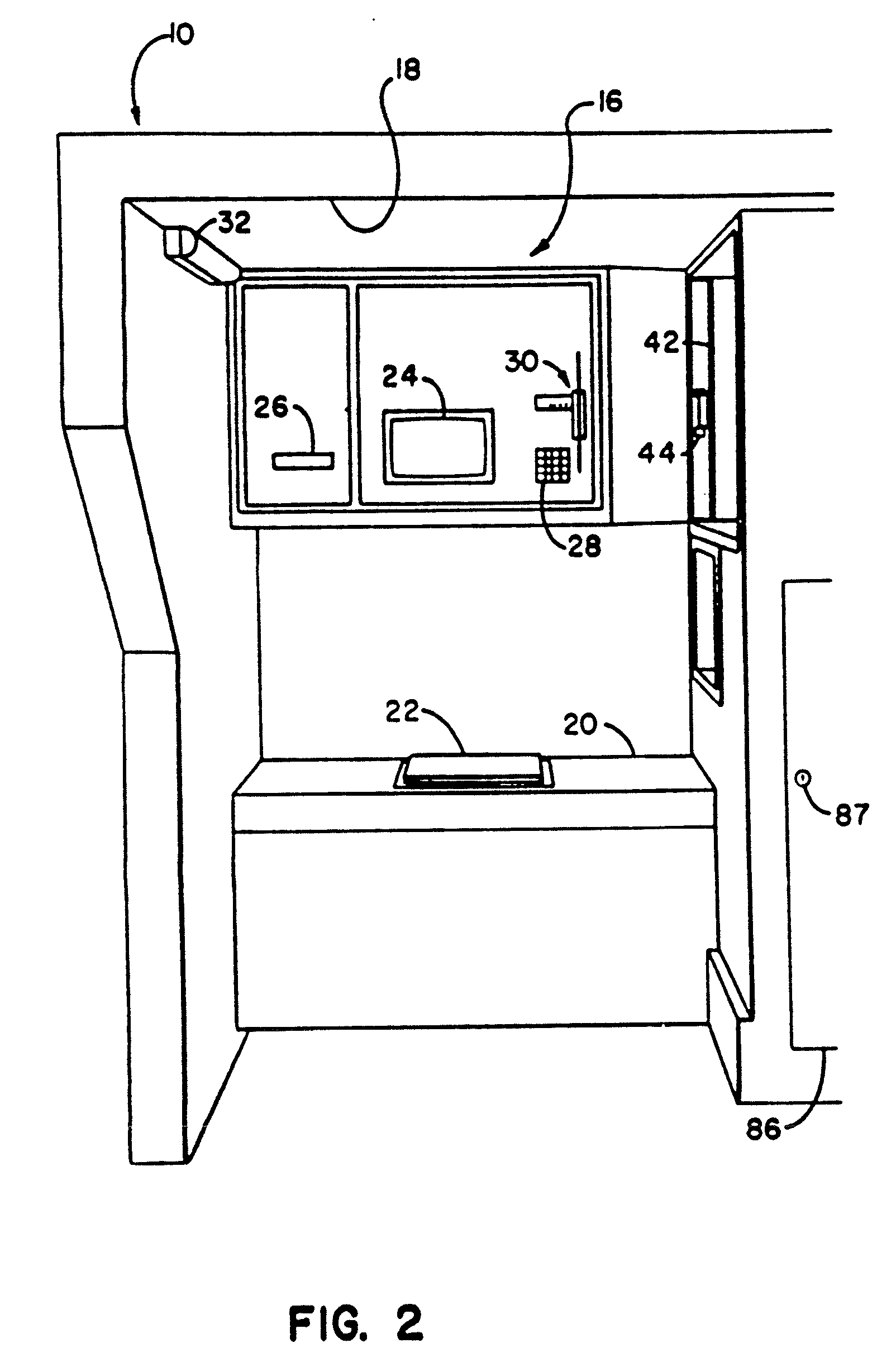
[0045]In the drawings, wherein like reference numerals designate corresponding structure throughout the views, and in particular in FIGS. 1-4, a system 10, constructed according to the invention for accepting and storing items for subsequent pick-up by a commercial carrier, includes an outer housing 12 which defines a storage area 14 for holding items such as packages or parcels. As best shown in FIGS. 1 and 2, system 10 further includes a customer interface area 16 which is positioned beneath a hooded overhang 18. Hooded overhang 18 provides privacy and shelter from the elements to a customer during use of the system 10. Interface area 16 includes a horizontal platform 20 upon which packages, parcels or personal items can be placed by a customer. Measuring indicia (not shown) are also preferably printed on platform 20 and on adjacent vertical walls of the housing 12 so that a customer can quickly measure the external dimensions of the item he or she intends to ship. An electronic s...

third embodiment

[0079]FIGS. 11-19 illustrate an improved system 310 for accepting and storing parcels and packages for subsequent pick-up by a commercial carrier which is constructed in accordance with the invention. As shown in FIG. 11, system 310 includes an outer housing 312 having an outer surface 314, an inner surface 316 (FIG. 13), and an enclosed customer interface area 318 that can be accessed by a customer by means of a door 320.

[0080]FIG. 12 is a closer view of the customer interface area 318. Customer interface area 318 includes a display device such as a CRT 322, a keyboard 324, a label printer 326, and a credit card reader 328. Customer interface area 318 further includes an outer door 330 with a handle 332 adapted for gripping by a customer to provide selective access to an intermediate holding space 334 for holding the package before the customer relinquishes control of it. As shown in FIG. 17, a magnetic lock 254 is provided for locking the outer door 330 in a closed position, as wa...

fourth embodiment

[0113]FIGS. 20-22 illustrate a stand alone automated shipping system 700 constructed in accordance with the invention for generating an appropriate mailing label for application to a parcel, package or envelope for shipment via a commercial carrier.

[0114]The system illustrated in FIG. 20 is designed for maximum efficiency in a high traffic retail environment such as grocery and hardware stores. It is operated by the customer so that retail store employees are not tied up by the complicated paperwork, weighing and calculating charges previously involved in the shipping of small packages. Also, since all data is transferred directly from the customer to the carrier via the system 700, the liability due to error and omissions of the retail employees is greatly reduced.

[0115]In this embodiment of the invention, information provided by the customer is used to generate an appropriate mailing label which is then applied to the parcel, package or envelope by the customer. The parcel, packag...


PUM


Abstract

A system for accepting and storing items for subsequent pickup by a commercial carrier includes a storage area which is defined by an outer housing, and a customer interface area that includes a weighing unit and a unit, such as a magnetic card reader, for accepting payment from a customer. The system may also include a control system that accepts address information from the customer through a key pad, and then instructs a printer to print an address label for the item. The system includes safeguards which prevent unauthorized access to the storage area, and will not provide a receipt to the customer until internal sensors verify deposit of the item. A manifest printer may also be provided for the benefit of the commercial carriers who service the system, to print out a summary of the transactions that pertain to each carrier. Alternatively, no storage area is provided. Instead, the item is given to a human attendant, such as a check out clerk of a grocery or hardware store and the like, with the appropriate mailing label for validation of receipt of the item by the attendant.

Description

[0001]This application is a Continuation of Ser. No. 08 / 845,012, filed Apr. 22, 1997, now U.S. Pat. No. 5,831,220, which was a division of Ser. No. 08 / 235,290, filed Apr. 29, 1994, now U.S. Pat. No. 5,656,799, which was a Continuation-in-part of U.S. patent application Ser. No. 07 / 903,342, filed on Jun. 24, 1992, now U.S. Pat. No. 5,340,948, which is a Continuation-in-part of U.S. patent application Ser. No. 07 / 683,243, filed on Apr. 10, 1991, now U.S. Pat. No. 5,233,532. The disclosures of the above-identified documents are hereby incorporated by reference as if set forth fully herein.BACKGROUND OF THE INVENTION[0002]1. Field of the Invention[0003]This invention relates to the commercial shipping and delivering industry. More specifically, this invention relates to an automated unit for preparing an appropriate mailing label, for validating receipt from a customer of a parcel, package, letter or other item for shipment, and / or for collecting and holding parcels, packages, letters a...

Claims


Application Information

Patent Timeline
Patent Type & Authority Applications(United States)
IPC IPC(8): G01G19/413G06F17/00G06Q20/00G01G19/00G01G19/414G06Q20/20G07B17/00G07F7/00G07F17/12G07F17/26
CPCG01G19/005G07F17/26G01G19/4148G06Q20/204G07B17/00193G07B17/00467G07B17/00661G07B2017/0004G07B2017/00209G07B2017/00225G07B2017/00233G07B2017/00274G07B2017/0037G07B2017/00685G07B2017/00701G07F5/26G07F17/0014G07F17/12G01G19/4144G07F17/13
Inventor RAMSDEN, GARY W.LILES, KENNETH WAYNE
Owner RAMSDEN GARY W
Learn More