Accumulator with pickup tube

Inactive Publication Date: 2005-04-21
HALLA CLIMATE CONTROL CANADA
View PDF71 Cites 23 Cited by
  • Summary
  • Abstract
  • Description
  • Claims
  • Application Information

AI Technical Summary

Benefits of technology

[0022] In practice some pressure drop is introduced in the accumulator because the flow is not incompressible. There is a minimum required pressure differential that must be incurred to return the oil to the compressor. The simplicity of certain embodiments of the present invention eliminates (or reduces) the existence of incidental elements that contribute to pressure drop. Oil is thus returned to the compressor in a more efficient fashion.
[0023] The pickup tube also minimizes the return of liquid to the compressor at switch-off, because the pickup tube is open at the top and hence cannot function as a siphon. As well, because the gas flow after switch-off is due primarily to migration (refrigerant evaporating from warm areas of the system and condensing at cooler places), and the velocity of migrating refrigerant is quite small, the pressure drop generated at the restriction will be quite small as well, and hence only minimal liquid, if any, will be withdrawn from the reservoir at switch-off.
[0024] In accordance with a further embodiment of the present invention, there is provided an accumulator which is relatively small, has few components, and is relatively easy to manufacture, all of which results in decreased cost. The relatively small size also makes embodiments of the present invention easier to package into systems. Further, the relatively large unobstructed reservoir in the accumulator allows for the possibility of other features to be incorporated into the accumulator, such as, for example, desiccant and/or coils for heat exchange, if desired.
[0025] In accordance with a further aspect of the present invention, there is provided an accumulator especially for automotive use embodying an outer housing consisting of sides and ends which are welded, crimped, or otherwise hermetically joined together, with one or more inlets, one or more outlets, and ports piercing or connecting through the ends and sides as required, and a deflector and an outlet tube or passage, with a restriction in the outlet passage to increase the flow velocity therein. A pickup tube, or other passage, is connected in communication with the restriction. The pickup tube extends to the bottom (or near the bottom) of the reservoir to facilitate liquid pickup. The restriction effect is used to meter liquid from the reservoir into the flow of gas through the outlet tube. There may also be a container, either of rigid or

Problems solved by technology

However even when the outlet is at or near the bottom of the accumulator, a riser tube is typically required to prevent the reservoir from

Method used


Image

  • Accumulator with pickup tube
  • Accumulator with pickup tube
  • Accumulator with pickup tube

Examples


Embodiment Construction

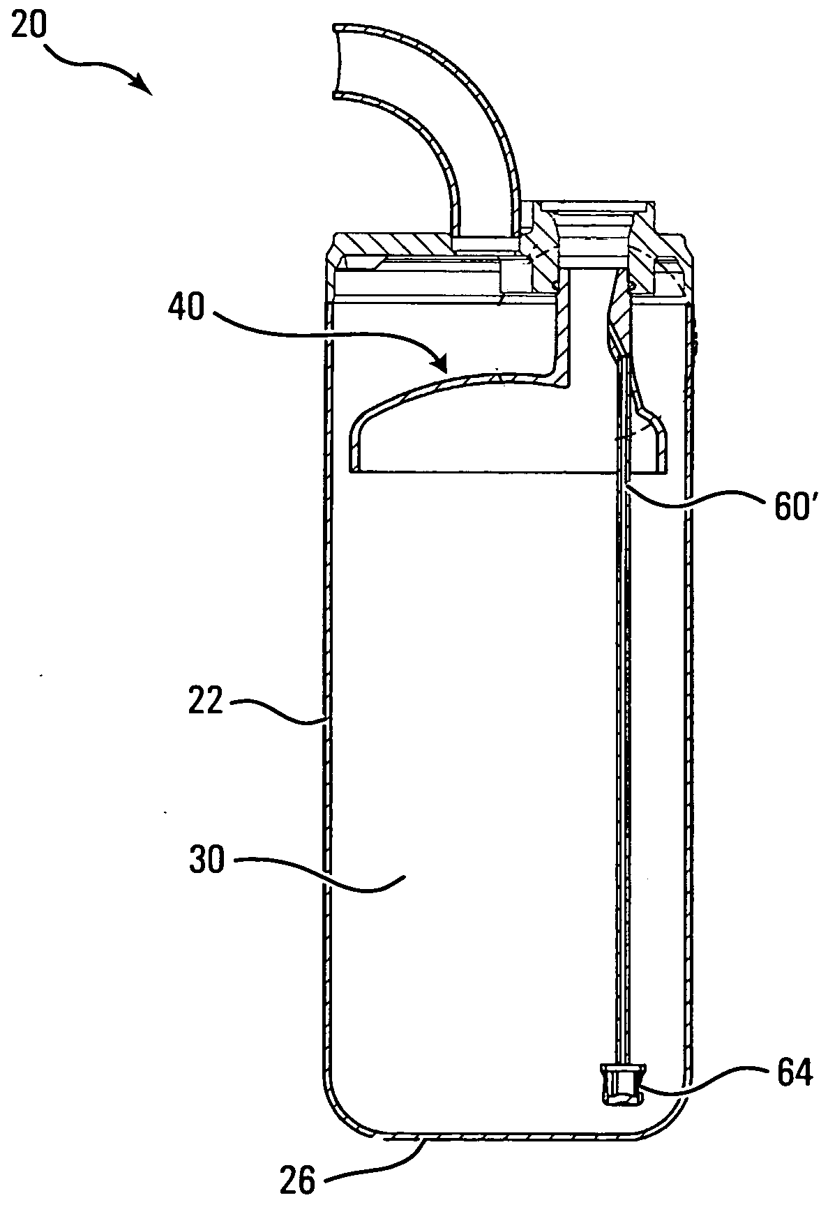
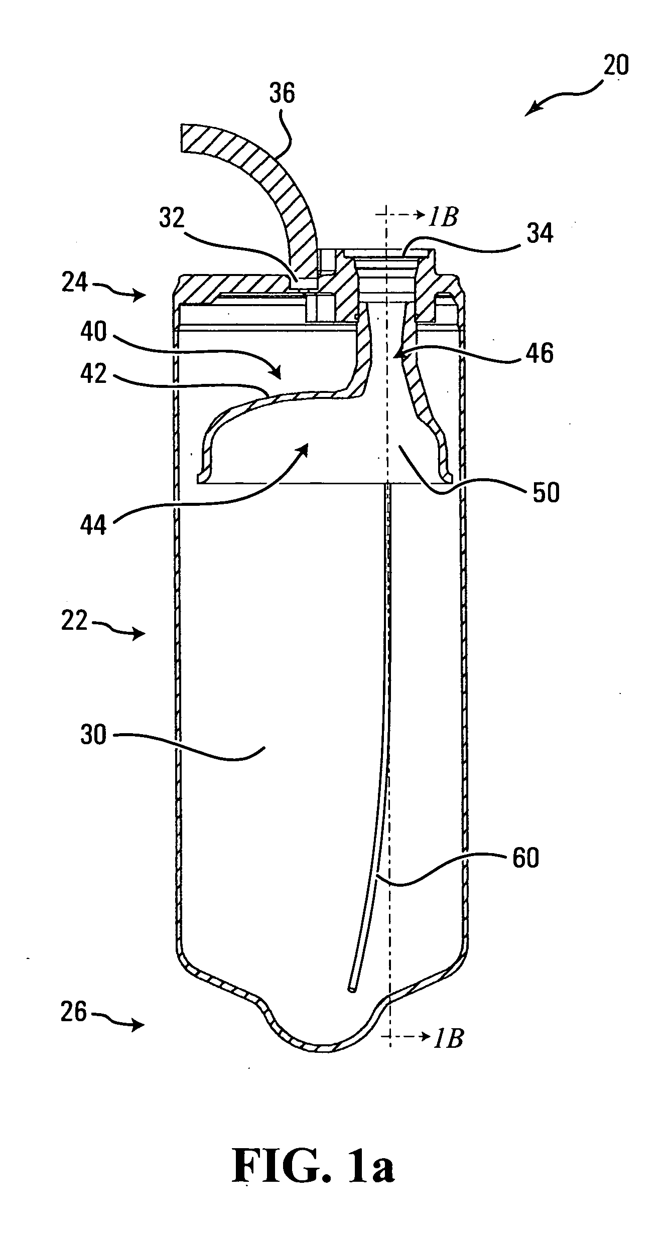
[0054] A sectional side view of an accumulator 20 is shown in FIG. 1a. The accumulator has a body 22 and a cap 24.

[0055] The body 22 is generally cylindrical, with an open top end, and a closed bottom end or floor 26. The bottom end 26, in this embodiment, is sloped inwards, with a depression or sump around and near the center. The volume within the accumulator 20 may be referred to as a reservoir 30.

[0056] The cap 24 is formed to fit securely over the top end of the body 22. The cap 24 has in inlet hole (or inlet port or inlet opening) 32 and an outlet hole (or outlet port or outlet opening) 34 formed therein. An inlet line 36 is secured to the inlet hole 32. The cap 24 is formed of a suitable material, such as aluminum, for example.

[0057] The cap 24 is secured to the body 22 by welding, swaging, heat or ultrasonic staking, gluing or some other suitable technique.

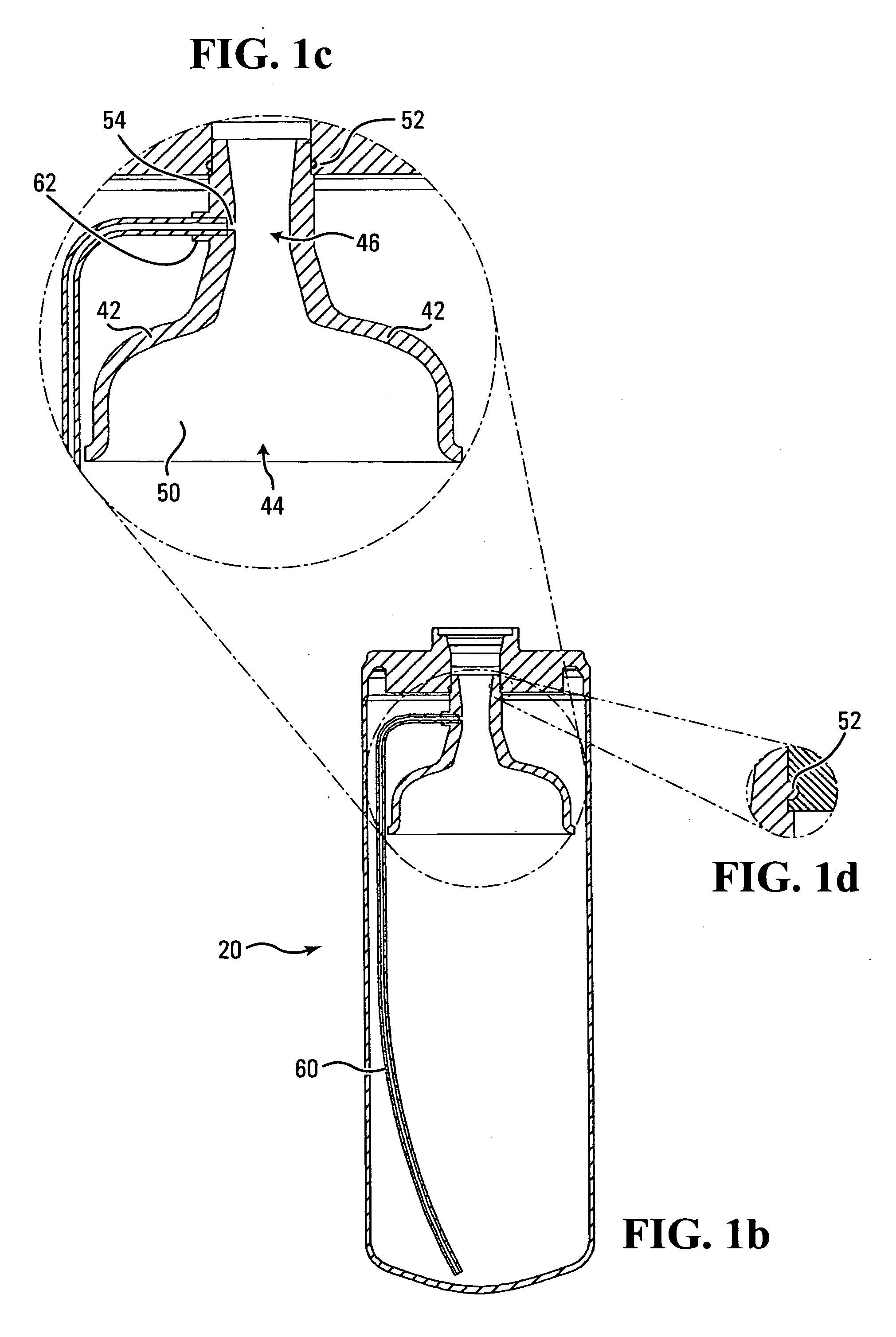
[0058] A deflector 40 is secured to (or in communication with) the outlet port 34. The deflector 40 has an exterior ...


PUM


Abstract

A suction accumulator for refrigeration or air-conditioning system use, especially for automotive air conditioning system use, which comprises a “pickup tube” to withdraw liquid from a reservoir of the accumulator to return oil to the compressor. The accumulator has a deflector with an outlet tube, to help ensure that fluid does not flow directly from the inlet opening to the outlet opening of the accumulator. The relatively narrow second portion of the outlet tube is closer to the outlet opening than the first portion. The pickup tube is secured in communication with the relatively narrow second portion and optimises the oil return function, minimises restriction to refrigerant flow, maximises effective and actual reservoir volume, and minimises the amount of liquid delivered to the compressor at switch-off. Incorporating an electric heating element or a heat exchanger for engine coolant or exhaust allows the accumulator of the present invention to function as the evaporator when the refrigeration system is used in heat pump mode for heating applications.

Description

[0001] This application is a conversion from U.S. Provisional application No. 60 / 512,102.FIELD OF THE INVENTION [0002] The present invention relates to a new and improved suction accumulator for use in a refrigeration system, including air-conditioning (A / C) or heat pump systems, and may be used in an air-conditioning or heat pump system of a motor vehicle. BACKGROUND OF THE INVENTION [0003] Closed-loop refrigeration systems conventionally employ a compressor that is meant to draw in gaseous refrigerant at relatively low pressure and discharge hot refrigerant at relatively high pressure. The hot refrigerant condenses into liquid as it is cooled in a condenser. A small orifice or valve divides the system into high and low-pressure sides. The liquid on the high-pressure side passes through the orifice or valve and turns into a gas in the evaporator as it picks up heat. (Some systems operate in “transcritical” mode, where the hot refrigerant is merely cooled in the high side heat excha...

Claims


Application Information

Patent Timeline
IPC IPC(8): F25B31/00F25B43/00
CPCF25B31/004F25B43/006F25B2500/01F25B2400/03F25B2341/0016
Inventor MCGREGOR, IAN ALEXANDER NEILDICKSON, TIMOTHY RUSSELLFINLAYSON, SCOTT MURRAY
Owner HALLA CLIMATE CONTROL CANADA
Why Eureka
Try Eureka