Method for driving liquid crystal display device

Active Publication Date: 2010-06-24
SEMICON ENERGY LAB CO LTD
View PDF47 Cites 64 Cited by
  • Summary
  • Abstract
  • Description
  • Claims
  • Application Information

AI Technical Summary

Benefits of technology

[0074]According to one embodiment of the pres

Problems solved by technology

Therefore, in flat panel displays typified by liquid crystal displays, in the case where processing for improving image quality is performed, a variety of problems may be caused.
For example, any of the following problems may be caused; the decrease in image quality, impossibility of display of correct

Method used


Image

  • Method for driving liquid crystal display device
  • Method for driving liquid crystal display device
  • Method for driving liquid crystal display device

Examples


embodiment 1

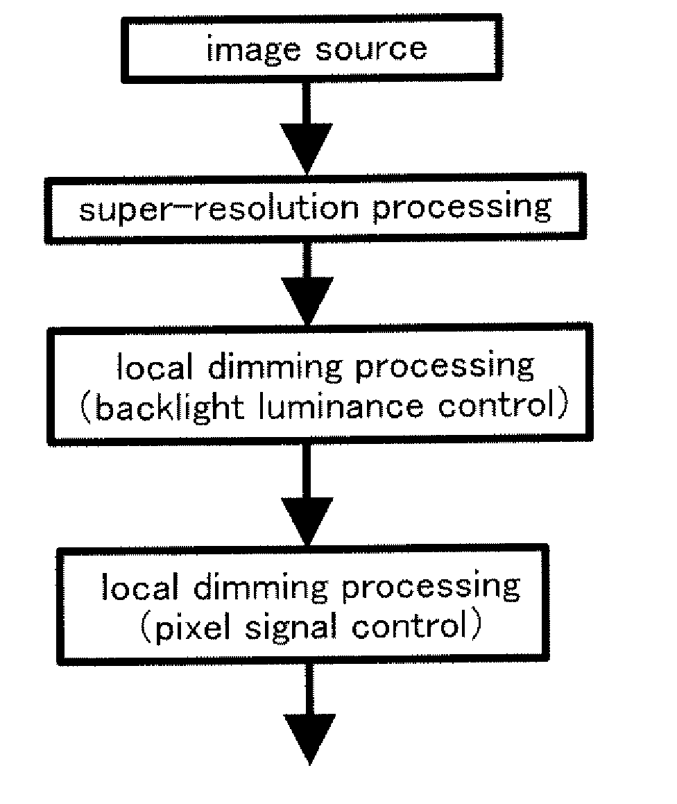
[0100]Super-resolution processing is processing for generating high-resolution images from low-resolution images. Alternatively, super-resolution processing is processing for restoring lost data in photographing, signal transmitting, or the like. Therefore, by performing super-resolution processing on averaged images whose details are crushed due to low resolution, images whose details can be accurately recognized can be generated. Thus, in the case of displaying such high-resolution images, high-quality images can be displayed. For example, in the case of a park where a great number of small stones are disposed or a tree having a great number of small leaves, by performing super-resolution processing on each small stone or each small leaf, each small stone or each small leave can be accurately recognized. In a similar manner, by performing super-resolution processing on a character which cannot be read due to blur, detailed parts of the character can be recognized. Thus, the charac...

embodiment 2

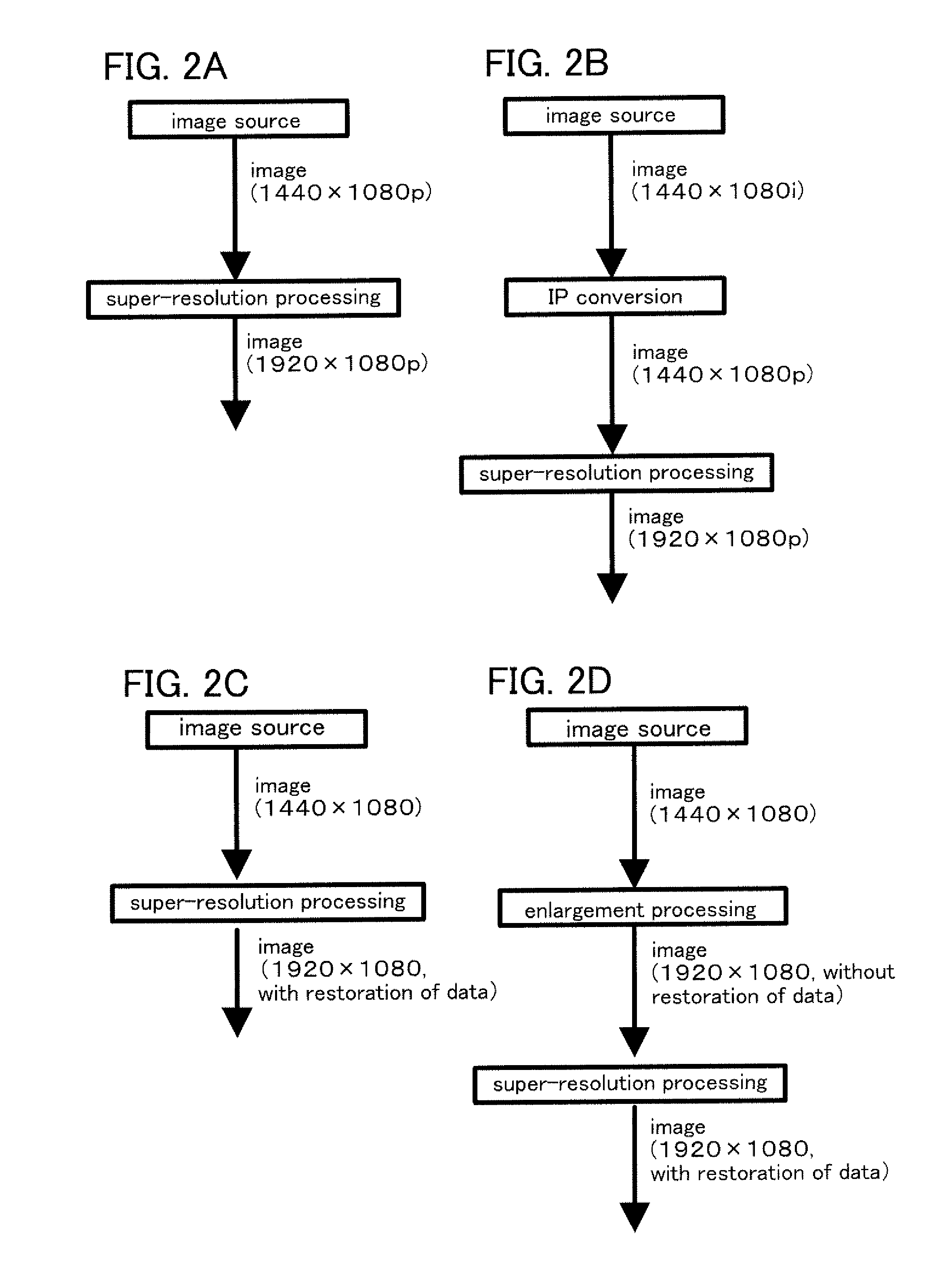
[0152]Next, examples of super-resolution processing technologies are described. By performing super-resolution processing, a high-resolution image can be displayed.

[0153]First, a moving region is detected and speed data of the region is extracted. That is, with respect to an image at given time, an optical flow, which is a vector illustrating the flow of each pixel, is calculated from two images before and after the image. Then, from the extracted speed data, the amount of positional deviation per image in the region is detected with accuracy of less than the size of one pixel. That is, from the calculated optical flow, the amount of positional deviation between images is calculated. Then, in accordance with the amount of detected positional deviation, the level of luminance between pixels is interpolated from a plurality of images in an image column. With such processing, a high-resolution image having resolution which is higher than physical resolution can be generated. Thus, it c...

embodiment 3

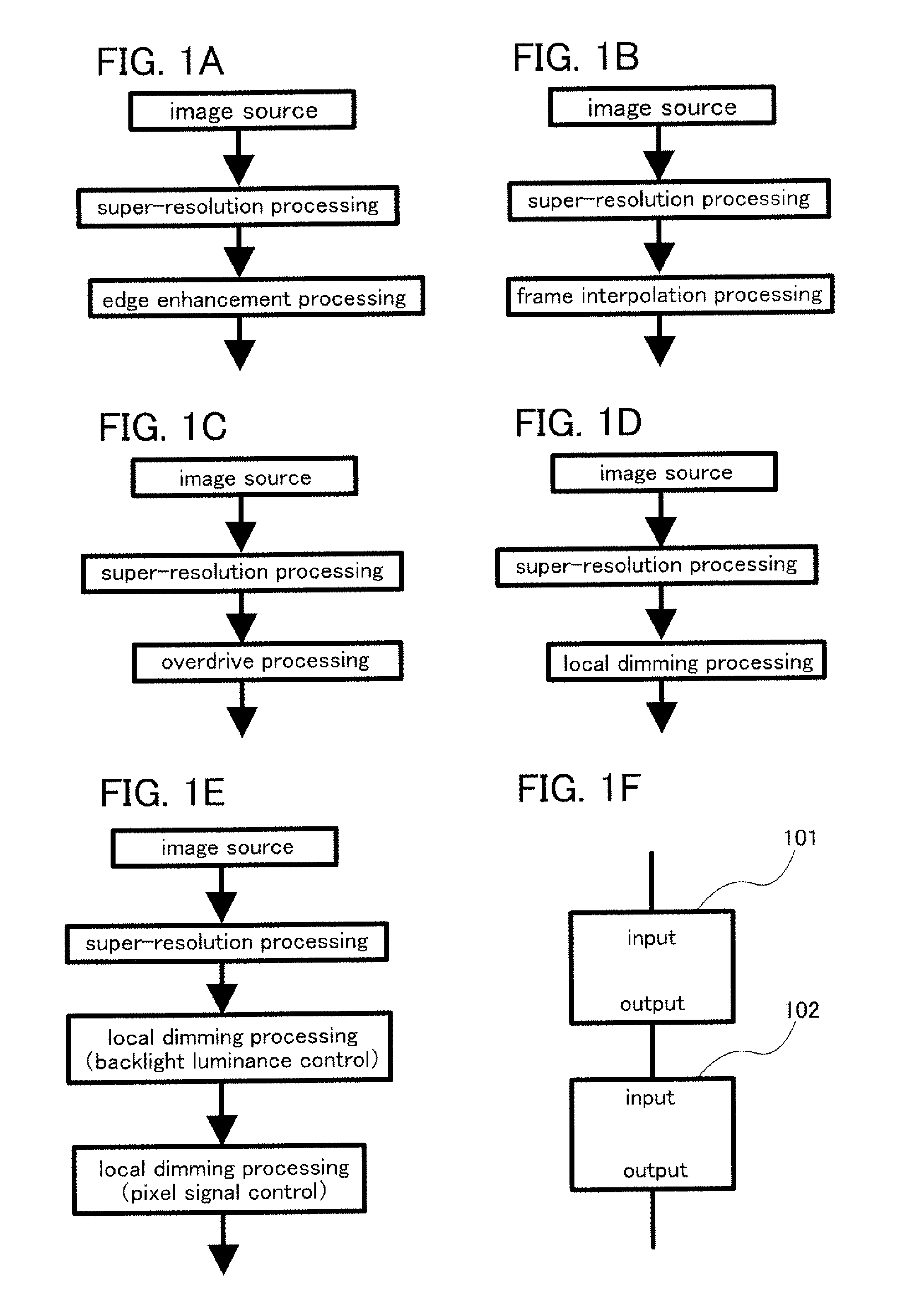
[0171]In Embodiments 1 and 2, the case is described in which super-resolution processing and different processing (e.g., edge enhancement processing, frame interpolation processing, overdrive processing, or local dimming processing of a backlight) are performed. Note that one example of this embodiment is not limited to this. In addition to super-resolution processing and different processing, processing such as edge enhancement processing, frame interpolation processing, overdrive processing, or local dimming processing of a backlight can be performed.

[0172]Therefore, the contents (may be some of the contents) or the drawings (may be some of the drawings) described in Embodiments 1 and 2 can be combined with or applied to this embodiment, for example.

[0173]For example, FIGS. 4A to 4D illustrate processing flows in the case where different processing is performed in addition to super-resolution processing and edge enhancement processing. That is, the processing flows illustrated in ...


PUM


Abstract

A low-resolution image is displayed at high resolution and power consumption is reduced. Resolution is made higher by super-resolution processing. Then, display is performed with the luminance of a backlight controlled by local dimming after the super-resolution processing. By controlling the luminance of the backlight, power consumption can be reduced. Further, by performing the local dimming after the super-resolution processing, accurate display can be performed.

Description

TECHNICAL FIELD[0001]The present invention relates to display devices, liquid crystal display devices, semiconductor devices, production methods thereof, or methods for using the display devices, the liquid crystal display devices, or the semiconductor devices. In particular, the present invention relates to driving methods of display devices, liquid crystal display devices, semiconductor devices, or the like, or signal processing methods thereof.BACKGROUND ART[0002]In recent years, flat panel displays typified by liquid crystal displays have been widely used. In addition, flat panels have been further improved in many respects. One of specifications of flat panels is resolution (or the number of pixels). Resolution has also been drastically improved.[0003]Therefore, a super-resolution processing technology, which is a technology for converting low-resolution images into high-resolution images, has been studied (see References 1 to 3).REFERENCE[0004]Reference 1: Japanese Published P...

Claims


Application Information

Patent Timeline
IPC IPC(8): G09G5/10G09G3/36G09G5/02
CPCG09G3/3426G09G3/3648G09G3/3655G09G2300/0426G09G2310/0229G09G3/36G09G2320/0646G09G2340/0435H04N5/142H04N7/0117H04N7/0125G09G2320/0252G02F1/1362H01L27/1214H01L29/7869G02F2202/10G09G3/3406G09G2320/062G09G2330/021G09G2340/0407G02F1/133603G02F1/133606G02F1/133608
Inventor KIMURA, HAJIME
Owner SEMICON ENERGY LAB CO LTD
Why Eureka
Try Eureka