Device for controlling throttle valve

a technology of throttle valve and control device, which is applied in the direction of electric control, combustion engines, machines/engines, etc., can solve the problems of degrading the durability and reliability of the sensor, the cost of the sensor itself is almost as high as the motor, and the output value of the sensor changes, so as to improve the durability and reliability, reduce the cost of the sensor, and the effect of excellent durability

Inactive Publication Date: 2005-12-20
HITACHI LTD
View PDF10 Cites 4 Cited by
  • Summary
  • Abstract
  • Description
  • Claims
  • Application Information

AI Technical Summary

Benefits of technology

[0005]In contrast, in the case of the non-contact type sensor using hall effect, the durability can be improved since there is no contact point at the sensor. However, the non-contact type sensor has a cost problem that a hall IC for calculating the position based on the output is required in addition to the hall element of the detection unit and further at least two sets are required in use in a view point of the reliability. Further, although the hall IC is arranged to digitize the output of the hall element and obtain the position by using a signal processing method, this calculation time causes the delay of the sensor. In the case of feedback-controlling the position of the throttle valve in the electronic control throttle device, as compared with the contact-type potentiometer which has little delay, the non-contact type sensor using hall effect has a problem that hunting likely occurs due to the delay of the detected phase of the throttle valve.
[0006]Accordingly, an object of the present invention is to provide a control device for a throttle valve which, by dispensing a position sensor for the throttle valve, can reduce a cost of the sensor and which is excellent in durability and reliability and is reduced in its control delay.
[0007]In order to attain the aforesaid object, the present invention is arranged in a manner that in a control device for a throttle valve which includes, an air flow sensor for detecting a flow rate of air flowing through a intake pipe of an internal combustion engine, a motor for driving the throttle valve disposed in the intake pipe, and control means for controlling driving operation of the motor, wherein the throttle valve is controlled so that a flow rate of air passing through the throttle valve coincides with an air flow rate required for the engine, the control device for a throttle valve is arranged in that the control means feedback-controls an output of the air flow sensor so that a difference between the output of the air flow sensor and the air flow rate required for the engine reduces.
[0008]According to such a configuration, since a position sensor for the throttle valve is dispensed, a cost of the sensor can be reduced, durability and reliability can be made excellent and control delay can be reduced.

Problems solved by technology

However, the potentiometer of the contact-type has a problem that the durability and reliability thereof is degraded since the brush or the contact surface of the resistor is worn away or foreign material is deposited on the resistor as being used and hence the output value of the sensor changes.
However, in this case, the cost of a sensor itself is almost as high as a motor.
In other words, the potentiometer of the contact-type has problems of the cost as well as the durability and reliability.
Further, since a memory capacity and an execution speed of the fail-safe software relating to the position sensor are several times or more as large as those of a controller main body, and so there arises a problem that a range of microcomputers capable of being used is limited.
However, the non-contact type sensor has a cost problem that a hall IC for calculating the position based on the output is required in addition to the hall element of the detection unit and further at least two sets are required in use in a view point of the reliability.
Further, although the hall IC is arranged to digitize the output of the hall element and obtain the position by using a signal processing method, this calculation time causes the delay of the sensor.
In the case of feedback-controlling the position of the throttle valve in the electronic control throttle device, as compared with the contact-type potentiometer which has little delay, the non-contact type sensor using hall effect has a problem that hunting likely occurs due to the delay of the detected phase of the throttle valve.

Method used


Image

  • Device for controlling throttle valve
  • Device for controlling throttle valve
  • Device for controlling throttle valve

Examples


Embodiment Construction

[0022]The configuration and operation of a control device for a throttle valve according to an embodiment of the present invention will be explained with reference to FIGS. 1 to 10.

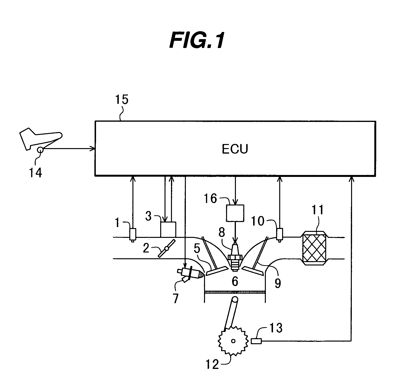
[0023]First, the explanation will be made with reference to FIG. 1 as to the system configuration of a direct fuel injection engine using the control device for a throttle valve according to the embodiment.

[0024]FIG. 1 shows the system configuration of the direct fuel injection engine using the control device for a throttle valve according to the embodiment.

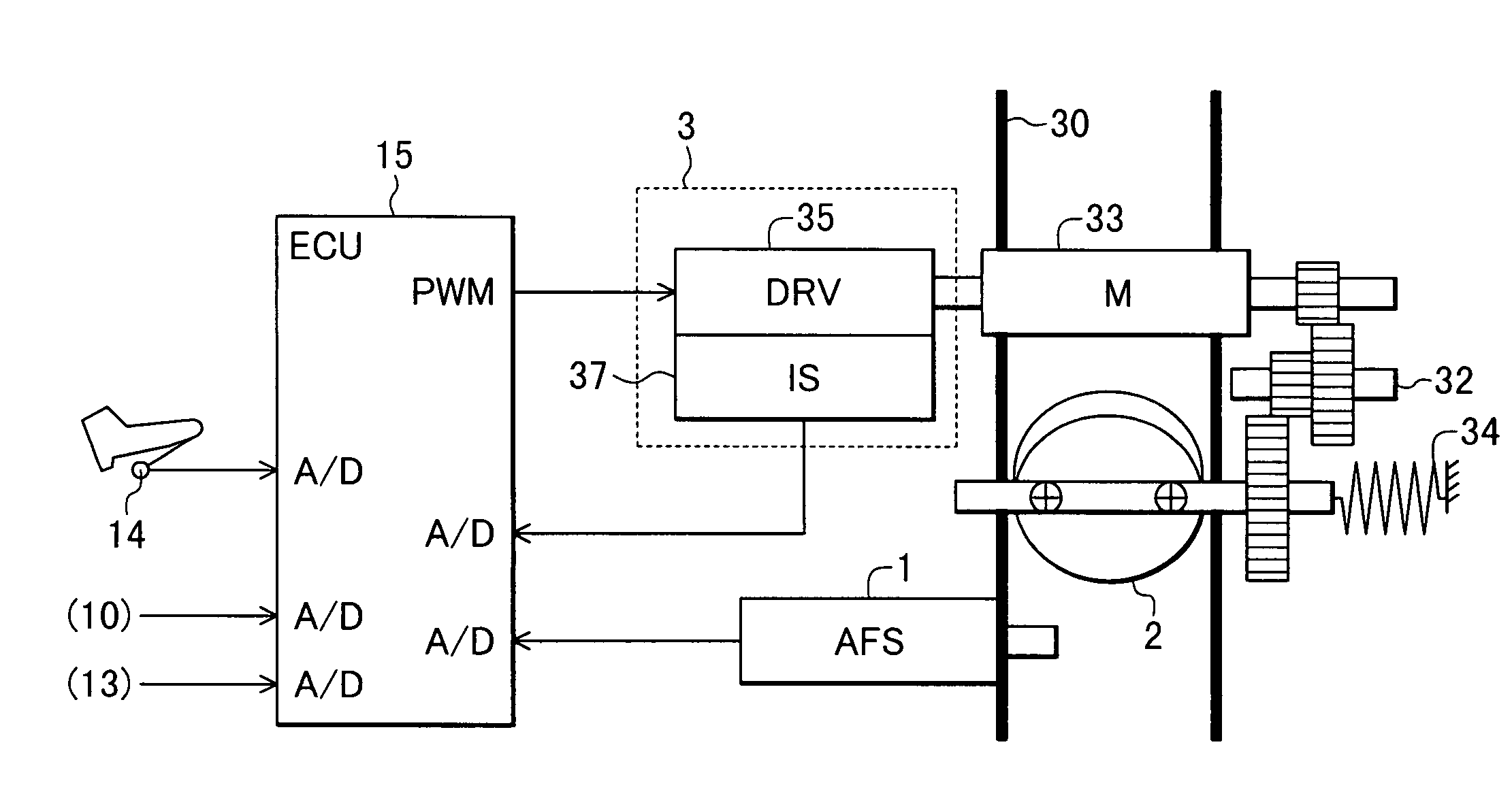
[0025]The intake system of the internal combustion engine is provided with an air flow sensor 1 for detecting a flow rate of intake air, a throttle valve 2 for adjusting a flow rate of intake air and intake valves 5. The opening degree of the throttle valve 2 is controlled by a throttle valve driving means 3. The throttle valve driving means 3 detects a motor current flowing through a motor for driving the throttle valve 2 and outputs the detected valu...


PUM


Abstract

A control device for a throttle valve, by dispensing a position sensor for the throttle valve, can reduce a cost of the sensor and which is excellent in durability and reliability and is reduced in its control delay. The control device includes an air flow sensor 1 for detecting an air flow rate flowing through a intake pipe of an internal combustion engine, a motor 33 for driving the throttle valve 2 disposed in the intake pipe and an ECU 15 for controlling the driving operation of the motor. The ECU 100 feedback-controls the output of the air flow sensor so that a difference between the output of the air flow sensor 1 and an air flow rate required for the engine reduces.

Description

TECHNICAL FIELD[0001]The present invention relates to a device for controlling a throttle valve for electronically controlling the throttle valve and, in particular, relates to a control device for a throttle valve which can preferably control a flow rate of air sucked into an internal combustion engine without using a position sensor.BACKGROUND ART[0002]Conventionally, in general, a throttle valve for controlling a flow rate of air sucked into an internal combustion engine is interconnected to an acceleration pedal through a wire so that a driver controls the opening and closing of the throttle valve by operating the acceleration pedal. In contrast, in recent years, an electronic control throttle device has been spread in which positions of an acceleration pedal and a throttle valve as well as an operating state are detected, then a target position of the throttle valve is obtained by a microcomputer, and the throttle valve is controlled by a motor so as to trace the target positio...

Claims


Application Information

Patent Timeline
Patent Type & Authority Patents(United States)
IPC IPC(8): F02D11/10F02D35/00F02D41/00F02D41/18
CPCF02D35/0007F02D41/0002F02D41/18F02D11/105F02D2041/1409Y02T10/42Y02T10/40
Inventor HOSHINO, MASATOSHIOOSUGA, MINORU
Owner HITACHI LTD
Why Eureka
Try Eureka