Method for producing a multifocal corneal surface using intracorneal microscopic lenses

Inactive Publication Date: 2006-03-07
KOZIOL JEFFREY E
View PDF19 Cites 53 Cited by
  • Summary
  • Abstract
  • Description
  • Claims
  • Application Information

AI Technical Summary

Benefits of technology

[0010]Accordingly, it is an object of the present invention is to provide an improved method for correcting the vision of an eye.
[0012]Still another object of the present invention is to provide a method for correcting the vision of an eye by inserting an intracorneal lens, without the lens substantially altering the shape of the cornea, so that undue tension is not experienced by the corneal flap.
[0014]Yet another object of the present invention is to provide a method for correcting the vision of an eye using multiple microscopic lenses, so that glare can be reduced or eliminated.
[0017]The foregoing objects are basically attained by a method for correcting vision of an eye, the eye having a cornea with an external surface and an optical axis, comprising the steps of separating a portion of the cornea to form first and second internal surfaces, and placing at least one microscopic lens in between the first and second internal surfaces, so that the external surface of the cornea is not substantially displaced.

Problems solved by technology

However, in many patients while the LASIK procedure is sufficient to correct distance vision it does not correct reading vision in patients who are presbyopic.
These procedures all induce a single corneal curvature change and do not correct both distance vision and close vision in a bifocal or multifocal manner.
Additionally, even though these existing intracorneal lenses are somewhat suitable for correcting distant vision disorders, they typically cause the eye to experience an undesirable side effect commonly referred to as a “halo effect”, which is a ring of light that a person will see in the eye having an implanted intracorneal lens.
Although the severity of the halo effect can vary depending on the shape of the intracorneal lens and the amount of direct and ambient light being received by the eye, the halo effect can cause the patient much annoyance.
Also, in certain instances, the halo effect can also adversely affect the patient's ability to read, drive a car and perform other routine activities requiring acute vision.
Additionally, many of these conventional techniques require relatively large lenses or corneal implants that stretch or expand the corneal surface to accommodate the intracorneal lens.
These large lenses can lead to corneal erosion, which is generally caused by corneal cells dying since the lens does not allow nutrients to flow through portions of the cornea.

Method used


Image

  • Method for producing a multifocal corneal surface using intracorneal microscopic lenses
  • Method for producing a multifocal corneal surface using intracorneal microscopic lenses
  • Method for producing a multifocal corneal surface using intracorneal microscopic lenses

Examples


Embodiment Construction

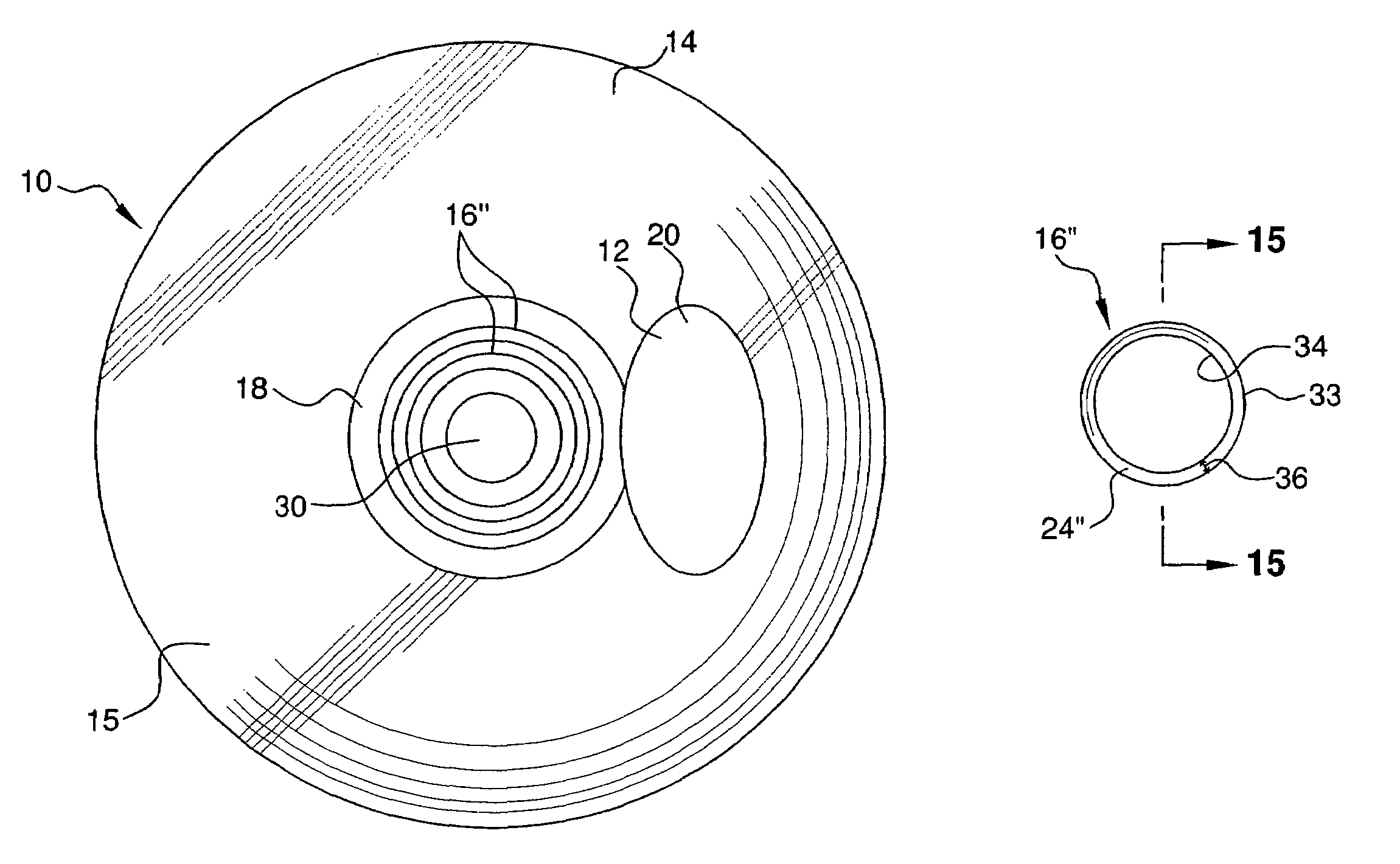
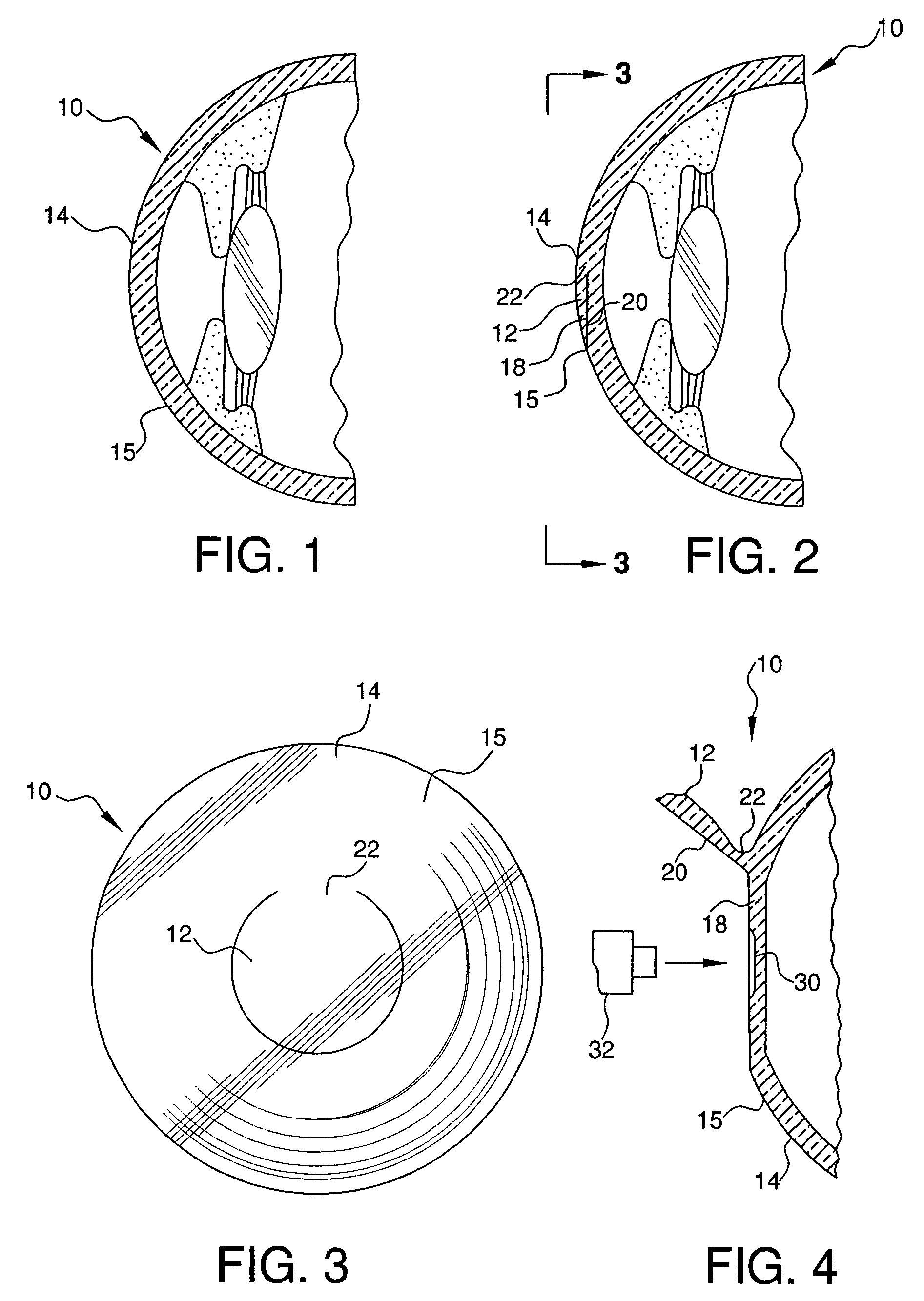
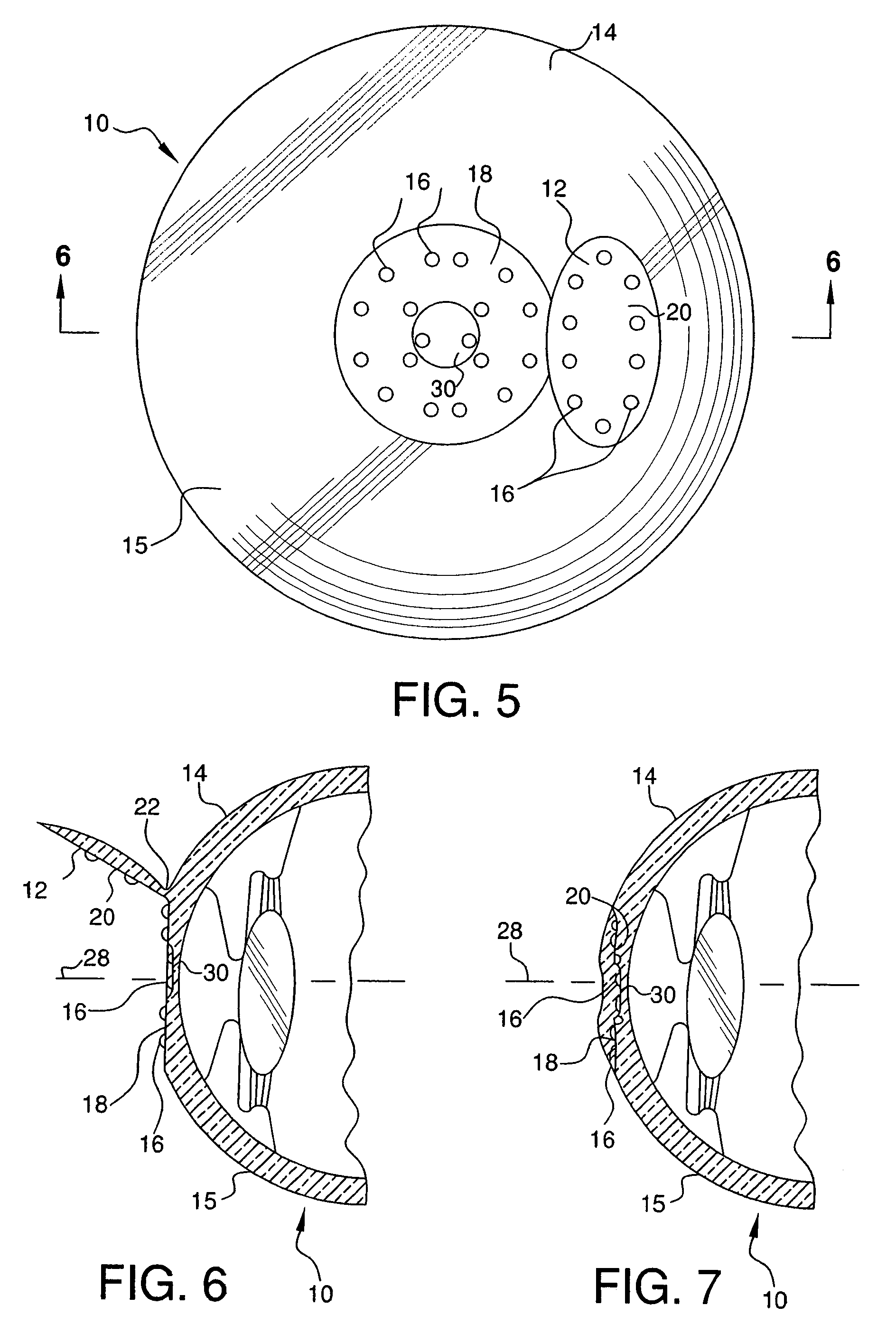
[0035]As seen in FIGS. 1–7, the refractive properties of eye 10 can be altered by creating a corneal flap 12 in the cornea 14, ablating the cornea to reshape the cornea and the external surface 15 of the cornea, and then placing multiple microscopic lenses or inlays 16 under flap 12.

[0036]To begin, the refractive error in the eye is measured using wavefront technology, or any other measurement device desired, as is known to one of ordinary skill in the art. For a more complete description of wavefront technology see U.S. Pat. No. 6,086,204 to Magnate, the entire contents of which is incorporated herein by reference. The refractive error measurements are then used to determine the proper correction necessary. For example, the information from the wavefront technology determines the proper portions of the cornea of the eye to be ablated, if necessary, and the proper power of the lenses 16 and / or the number of the lenses 16 to be implanted.

[0037]As seen in FIGS. 2 and 3, flap 12 is cre...


PUM


Abstract

A method for correcting vision of an eye, including the steps of separating a portion of the cornea to form first and second internal surfaces in the cornea, and then placing at least one microscopic lens in between the first and second internal surfaces in the cornea, so that the external surface of the cornea is not substantially displaced. In a preferred embodiment, the microscopic lenses can be placed in concentric circles around the main optical axis so that the lenses form multifocal or bifocal vision.

Description

CROSS-REFERENCE TO RELATED APPLICATION[0001]This application is a continuation application of Ser. No. 09 / 852,846, filed May 11, 2001, now U.S. Pat. No. 6,589,280, issued Jul. 8, 2003, the entire contents of which are herein incorporated by reference.FIELD OF THE INVENTION[0002]The present invention relates to implanting microscopic lenses in a live cornea of an eye to help correct the vision in the eye by producing a multifocal corneal surface. More particularly, the present invention relates to inserting microscopic lenses under a corneal flap after a surgical procedure, such as LASIK eye surgery, to correct the vision in the eye by producing a multifocal corneal surface without substantially displacing the external corneal surface.BACKGROUND OF THE INVENTION[0003]Conventional surgical techniques use ultraviolet light and short wavelength lasers to modify the shape of the cornea. For example, excimer lasers, such as those described in U.S. Pat. No. 4,840,175 to Peyman, which is in...

Claims


Application Information

Patent Timeline
IPC IPC(8): A61F2/14A61F9/013
CPCA61F9/013A61F2/147
Inventor KOZIOL, JEFFREY E.
Owner KOZIOL JEFFREY E
Why Eureka
Try Eureka