Signal processing system for construction machine

a technology of signal processing and construction machinery, applied in the field of construction machines, can solve the problems that the only use of tables can not meet the needs of all kinds of situations, and achieve the effect of reducing the number of times of the tonnage modification

Inactive Publication Date: 2006-03-28
NIHON KENKI CO LTD
View PDF5 Cites 30 Cited by
  • Summary
  • Abstract
  • Description
  • Claims
  • Application Information

AI Technical Summary

Benefits of technology

[0011]An object of the present invention is to provide a signal processing system for a construction machine, which can modify a maximum absorption torque of a hydraulic pump or a fuel injection state of a fuel injection device in any environments in an appropriately responsive way, and hence which enables the construction machine to sufficiently develop its performance.
[0033]With that feature, the communication control means is able to conveniently perform communication with respect to the external terminal.

Problems solved by technology

For that reason, even when the torque modification is made, as in the prior art, by preparing the tables in advance for environment factors related to the operation status of the prime mover, there is a possibility that, in some of working places and working conditions, the torque modification using only the tables is not sufficient to cope with all kinds of situations (e.g., in the case of the construction machine operating under conditions outside the varying ranges of the environment factors which have been assumed at the time of preparing the tables, or in the case where a table for the relevant environment factor has not been itself prepared).

Method used


Image

  • Signal processing system for construction machine
  • Signal processing system for construction machine
  • Signal processing system for construction machine

Examples


Embodiment Construction

[0048]One embodiment of the present invention will be described below with reference to FIGS. 1 to 10. In the following embodiment, the present invention is applied to an engine / pump controller in a hydraulic excavator.

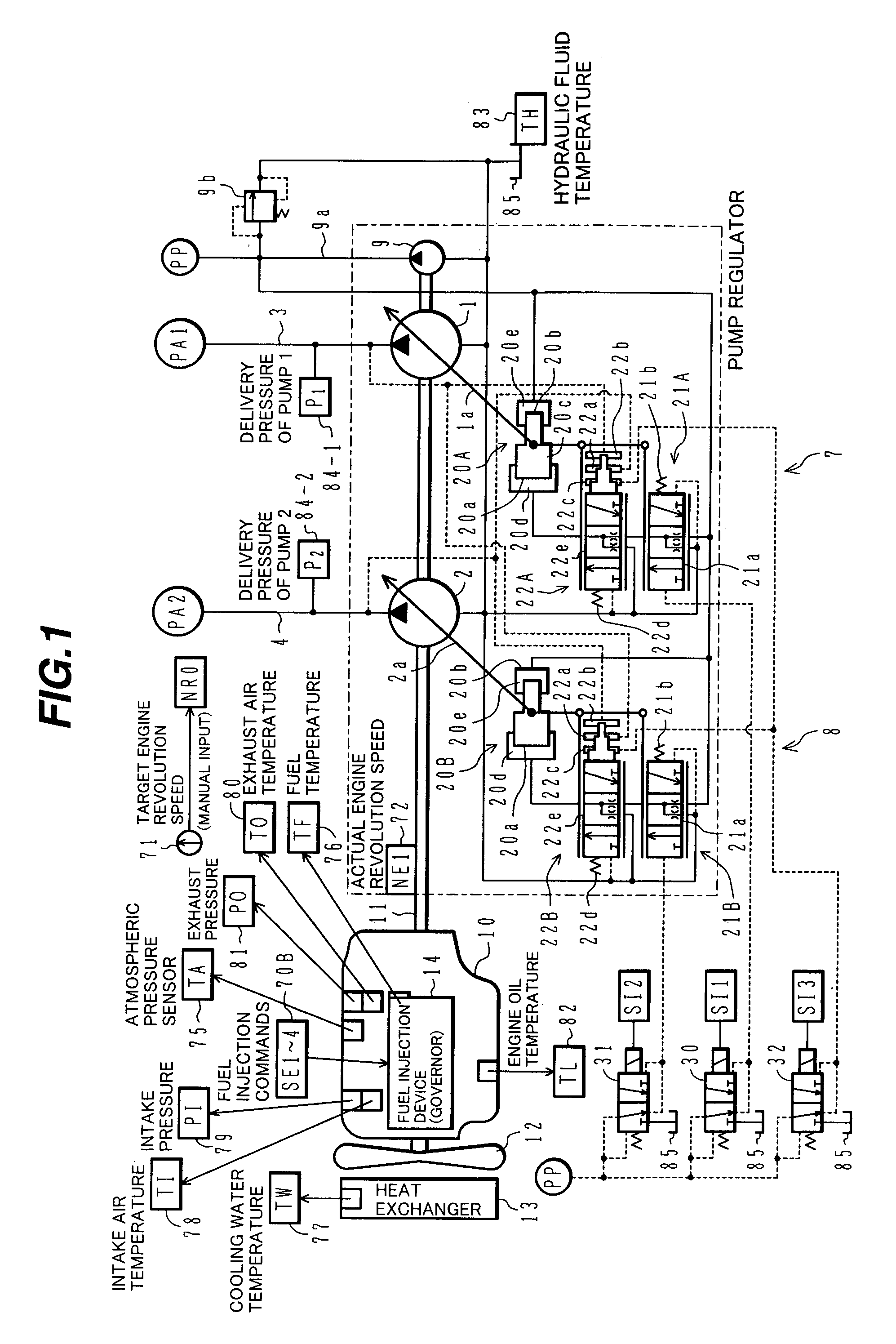
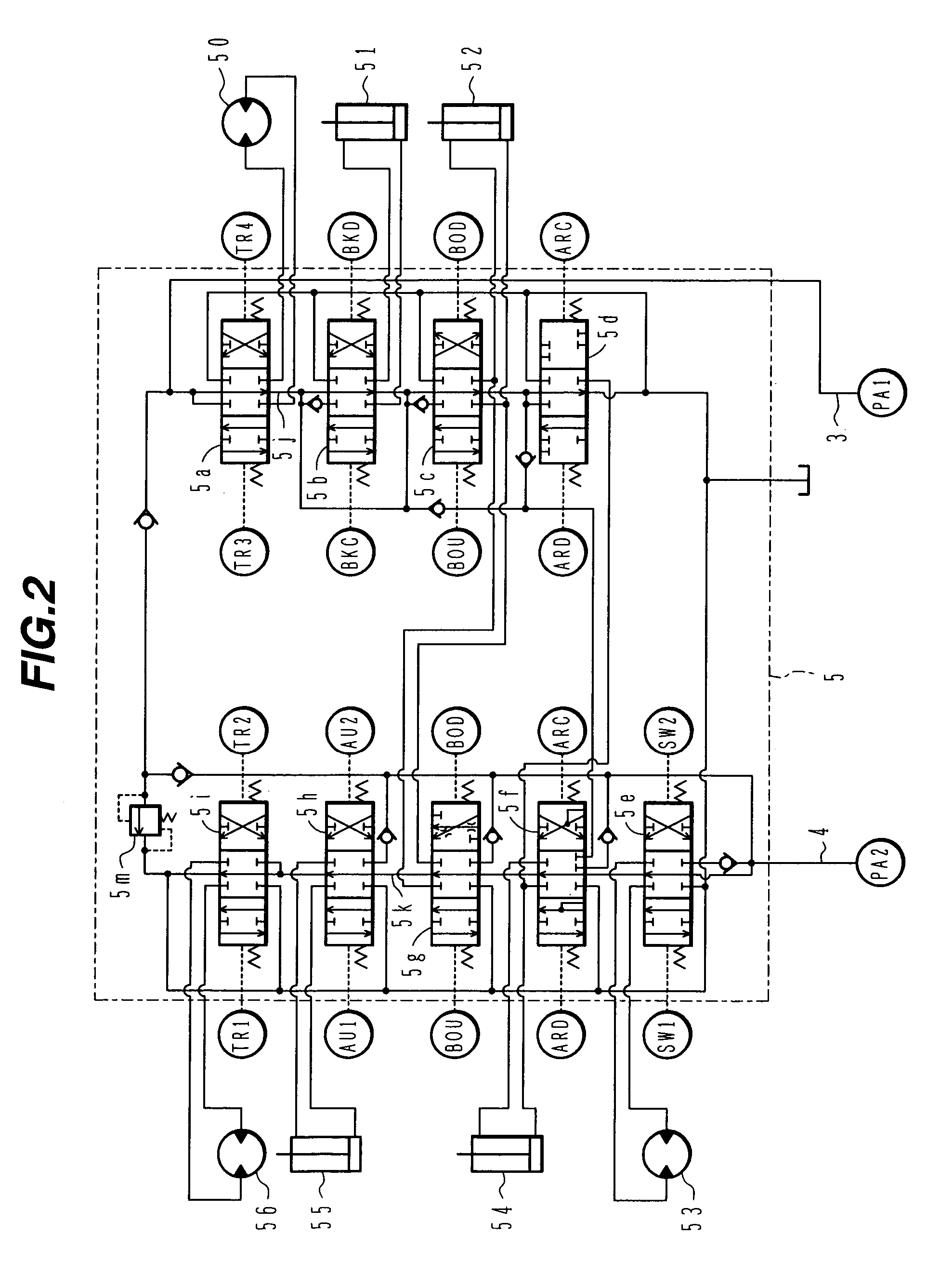
[0049]FIG. 1 is a hydraulic circuit diagram showing a part of a hydraulic drive system equipped in a hydraulic excavator to which a signal processing system for a construction machine according to the present invention is applied. In FIG. 1, numerals 1 and 2 denote variable displacement hydraulic pumps of, e.g., swash plate type. A valve unit 5 (see FIG. 2 described later) is connected to delivery lines 3, 4 of the hydraulic pumps 1, 2. A hydraulic fluid is sent to a plurality of hydraulic actuators 50 to 56 through the valve unit 5 for driving the actuators.

[0050]Numeral 9 denotes a fixed displacement pilot pump. A pilot relief valve 9b for holding the delivery pressure of the pilot pump 9 at a constant pressure is connected to a delivery line 9a of the pilot pump 9....


PUM


Abstract

A machine body controller 70A includes a modification control unit 70Ab for computing a torque modification value based on detected signals from environment sensors 75 to 83, and modifies a maximum absorption torque of a hydraulic pump controlled by a basic control unit 70Aa. An engine controller 70B includes a modification control unit 70Bb for computing an injection modification value based on detected the signals from the environment sensors 75 to 83, and modifies a fuel injection state of a fuel injection device 14 controlled by a basic control unit 70Ba. The controllers 70A, 70B further include computation element altering units 171, 181. A communication controller 70C downloads alteration data obtained from an external terminal 150 to the computation element altering units 171, 181, whereby corresponding computation elements contained in the modification control units 70Ab, 70Bb are altered. As a result, it is possible in any environments to approprately modify the maximum absorption torque of the hydraulic pump and the fuel injection state of the injection device, and to sufficiently develop the performance of a construction machine.

Description

TECHNICAL FIELD[0001]The present invention relates to a construction machine such as a hydraulic excavator, and more particularly to a signal processing system for a construction machine, which is suitably equipped in the construction machine.BACKGROUND ART[0002]A construction machine, such as a hydraulic excavator, generally includes a diesel engine as a prime mover, and performs necessary work by rotationally driving at least one variable displacement hydraulic pump by the diesel engine and driving hydraulic actuators with a hydraulic fluid delivered from the hydraulic pump. The diesel engine is provided with an input means, e.g., accelerator lever, for commanding a target revolution speed. The fuel injection volume is controlled in accordance with the target revolution speed, whereby the engine revolution speed is controlled.[0003]For such control of the engine and the hydraulic pump in the hydraulic construction machine, the so-called speed sensing control has hitherto been perf...

Claims


Application Information

Patent Timeline
Patent Type & Authority Patents(United States)
IPC IPC(8): F04B49/06F02D29/04F04B49/00F04B17/05F15B11/16
CPCF02D29/04F04B49/002F04B49/065F15B11/165F15B11/167F04B17/05F15B2211/88F04B2201/1202F15B2211/20523F15B2211/20553F15B2211/20584F15B2211/30505F15B2211/30525F15B2211/3056F15B2211/3116F15B2211/31576F15B2211/329F15B2211/50536F15B2211/50563F15B2211/575F15B2211/6054F15B2211/63F15B2211/6355F15B2211/66F15B2211/71F15B2211/865F04B49/06
Inventor NAKAMURA, KAZUNORIHIRATA, TOICHIARAI, YASUSHIKOWATARI, YOICHIYASUDA, GENWATANABE, HIROSHI
Owner NIHON KENKI CO LTD
Why Eureka
Try Eureka