Method and apparatus for transmitting multiple signal, method and apparatus for receiving multiple signal, multiple signal transmission method and multiplexer/demultiplexer

a signal transmission and multiplexing technology, applied in the direction of data switching by path configuration, time-division multiplexing selection, electrical apparatus, etc., can solve the problems of extremely low transmission efficiency, process redundantness, and decline in the transmission efficiency of sonet/sdh frame, so as to efficiently multiplex the signal

Inactive Publication Date: 2006-05-09
NEC CORP
View PDF7 Cites 31 Cited by
  • Summary
  • Abstract
  • Description
  • Claims
  • Application Information

AI Technical Summary

Benefits of technology

[0025]An object of the present invention is to provide a multiplexer/demultiplexer, which uses 8B/10B block coding, and efficie

Problems solved by technology

However, when a padding byte is inserted into a payload in order to multiplex the signal of which transmission speed unmatches with the multiplexing steps, transmission efficiency of the SONET/SDH frame declines.
Therefore, transmission efficiency is extremely low

Method used


Image

  • Method and apparatus for transmitting multiple signal, method and apparatus for receiving multiple signal, multiple signal transmission method and multiplexer/demultiplexer
  • Method and apparatus for transmitting multiple signal, method and apparatus for receiving multiple signal, multiple signal transmission method and multiplexer/demultiplexer
  • Method and apparatus for transmitting multiple signal, method and apparatus for receiving multiple signal, multiple signal transmission method and multiplexer/demultiplexer

Examples


Embodiment Construction

[0043]Next, detailed description will be made of an embodiment of the present invention with reference to the accompanying drawings.

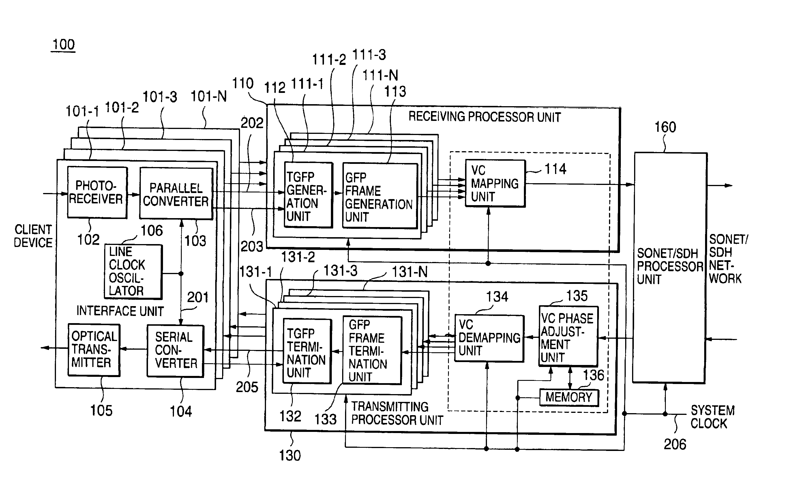
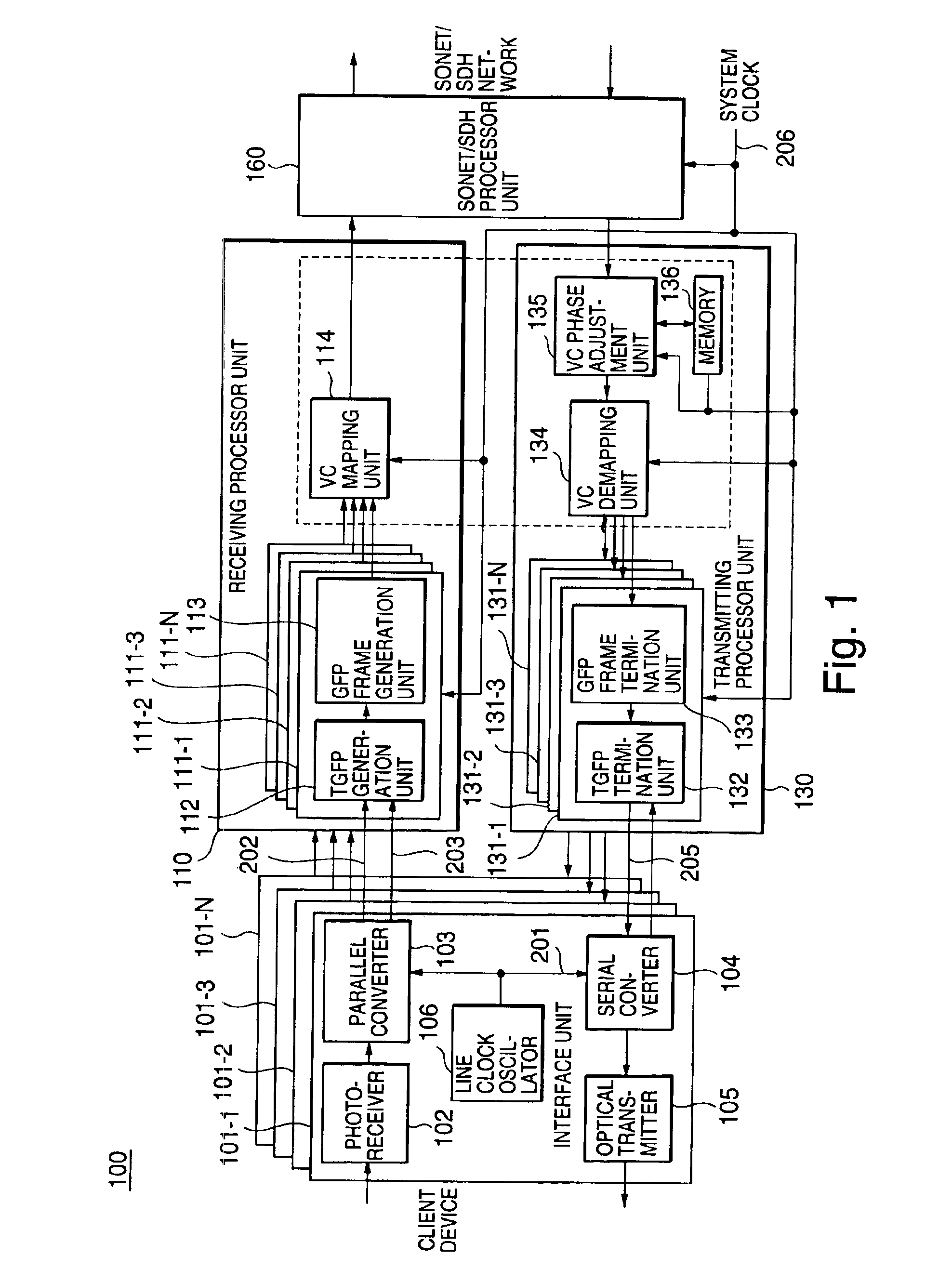
[0044]FIG. 1 is a block diagram showing a configuration of a data multiplexer / demultiplexer according to an embodiment of the present invention. Referring to FIG. 1, the data multiplexer / demultiplexer 100 of the embodiment comprises interface units 101-1 to 101-N, a receiving processor unit 110, transmitting processor unit 130, a SONET / SDH processor unit 160.

[0045]A not-shown network device, constituting a SONET / SDH network, is connected to the SONET / SDH processor unit 160. The network device is, for example, a SONET / SDH transmitter or a data multiplexer / demultiplexer similar to the present data multiplexer / demultiplexer.

[0046]The interface units 101-1 to 101-N are connected to a not-shown client device in accordance with a client protocol such as Gigabit Ethernet, Fibre Channel, ESCON or DVB-ASI. The client device is, for example, a computer for transm...


PUM


Abstract

A client channel receiving processor unit converts each reception client signal of a 10B-character form into a GFP frame form. A mapping unit maps the client signal of the GFP frame form on a channel of virtual concatenation. A SONET/SDH processor unit transmits or receives a SONET/SDH frame, in which a GFP frame is mapped, to/from a network. A demapping unit separates each channel of the SONET/SDH frame received by the SONET/SDH processor unit. A client channel transmitting processor unit detects the client signal of the GFP frame from each separated channel to convert the signal into a 10B-character form.

Description

BACKGROUND OF THE INVENTION[0001]1. Field of the Invention[0002]The present invention relates to a multiple signal transmission method and a multiplexer / demultiplexer for multiplex-transmission of data processed by a computer or the like. More specifically, the invention relates to a multiple signal transmission method and a multiplexer / demultiplexer for multiplexing data coded in an 8B / 10B block in a SONET / SDH frame, and then demultiplexing the data.[0003]2. Description of the Related Art[0004]Through SONET / SDH Network, a number of signals can be efficiently multiplexed to be transmitted for a long distance at a high speed in accordance with internationally standardized multiplexing steps. Conventionally, most of traffic transmitted through a network has been voice traffic. Thus, voice signals of mainly 64 Kbps have been multiplex-transmitted through the SONET / SDH Network.[0005]However, because of a recent increasing ratio of data traffic caused by popularization of Internet, the n...

Claims


Application Information

Patent Timeline
IPC IPC(8): H04L12/28H04J3/00H04J3/16H04Q11/04
CPCH04J3/1617Y10S370/907H04J2203/0094H04J2203/0089
Inventor KAMIYA, SATOSHI
Owner NEC CORP
Why Eureka
Try Eureka