Computer mouse on a glove

a mouse and glove technology, applied in the field of peripheral computer input devices, can solve the problems of increasing the incidence of carpel tunnel syndrome among mouse users, one mouse size certainly does not fit all hand sizes, and the general failure of attempts to achieve the effect of minimizing user strain and maximizing performan

Inactive Publication Date: 2006-06-06
DEANMARK TECH
View PDF16 Cites 43 Cited by
  • Summary
  • Abstract
  • Description
  • Claims
  • Application Information

AI Technical Summary

Benefits of technology

[0016]Yet another object of a preferred embodiment of the present invention is to provide a computer mouse on a glove, which is adjustable to the size of a user's hand and includes padding to minimize user strain and maximize performance.
[0025](g) the computer mouse on a glove of the present invention will permit a user to control up and down scrolling and paging functions without having to remove the user's hands from the computer keyboard.

Problems solved by technology

Those attempts have generally been unsuccessful because the human hand comes in many shapes and sizes.
Therefore, one size of computer mouse certainly does not fit all hand sizes.
The result has been increasing incidents of carpel tunnel syndrome amongst mouse users as they struggle to conform their hands to the currently available designs.
In addition to hand and arm strain, one major disadvantage of the conventional mouse design is that users often must spend valuable time searching their desktops to locate the mouse before using it.
This disrupts the creative process and hinders both user performance and productivity.
Some attempts have been made to solve these problems by locating a tracking device, such as a track ball or a sensor pad, right on the computer keyboard, but some find these devices awkward to use and difficult to master.
Moreover, such devices still require the user to remove his or her eyes from the display to find the exact location of the tracking device.
This process can interrupt work flow and reduce productivity.
Although the device described by Wambach does not require a surface over which a tracking device must be moved, it does require a great deal of skill and considerable practice for the user to be able to control a cursor on a video display with any degree of accuracy.
However, Butler makes no provision for using a tracking device that includes an optical sensor or for using a tracking device in contact with a surface.
Moreover, Butler's tracking device and mouse “click” buttons do not automatically turn “off” when not in use to permit typing, and do not automatically turn “on” again when required for moving the cursor and performing mouse “clicking” functions.
Further, Butler's design restricts movement of the hand during operation to small movements of the thumb and fingers required to activate the tracking device the mouse click buttons.
This results in reduced blood flow to the hand when compared to other mouse designs which require whole arm movements.

Method used


Image

  • Computer mouse on a glove
  • Computer mouse on a glove
  • Computer mouse on a glove

Examples


Embodiment Construction

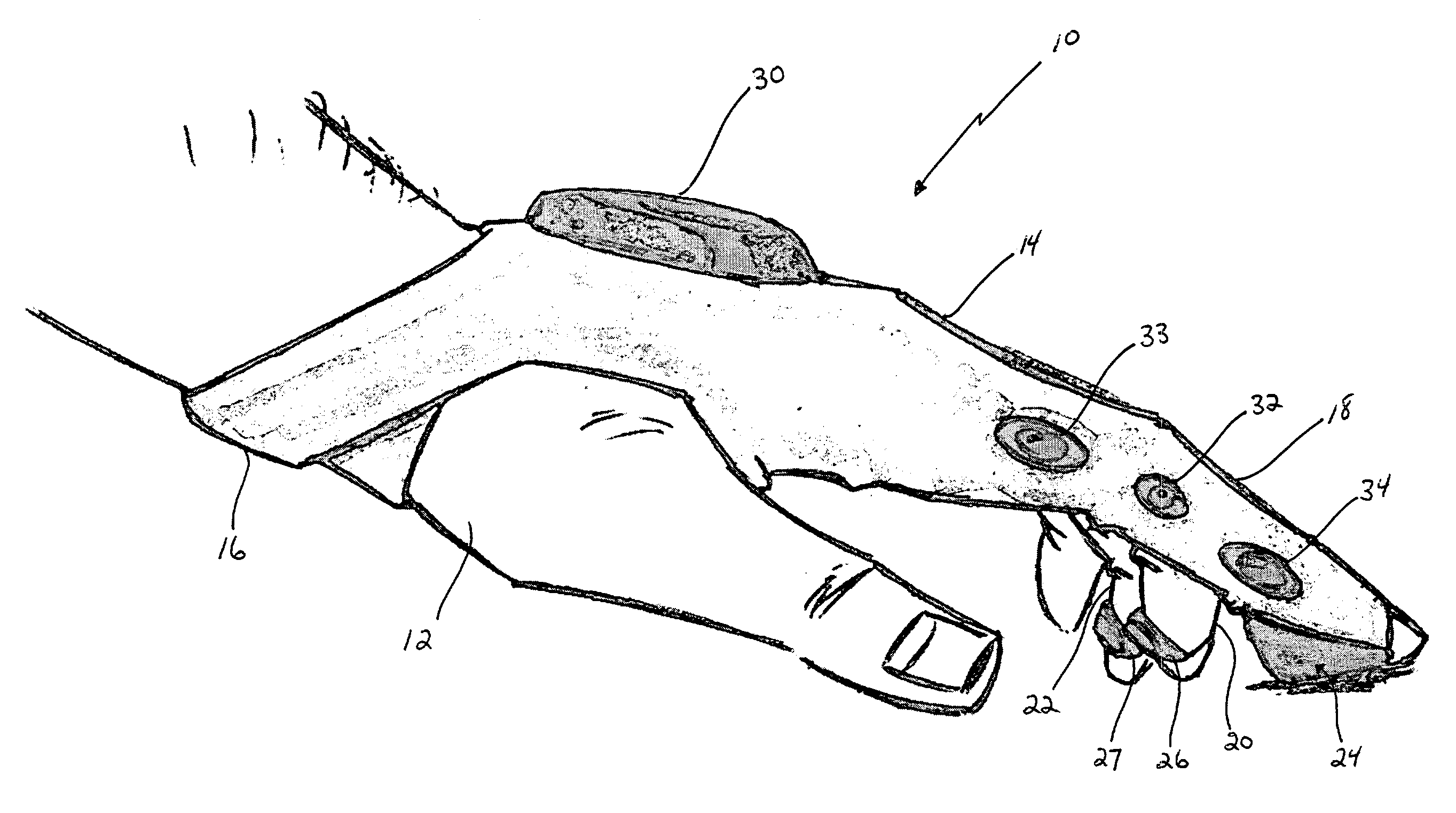
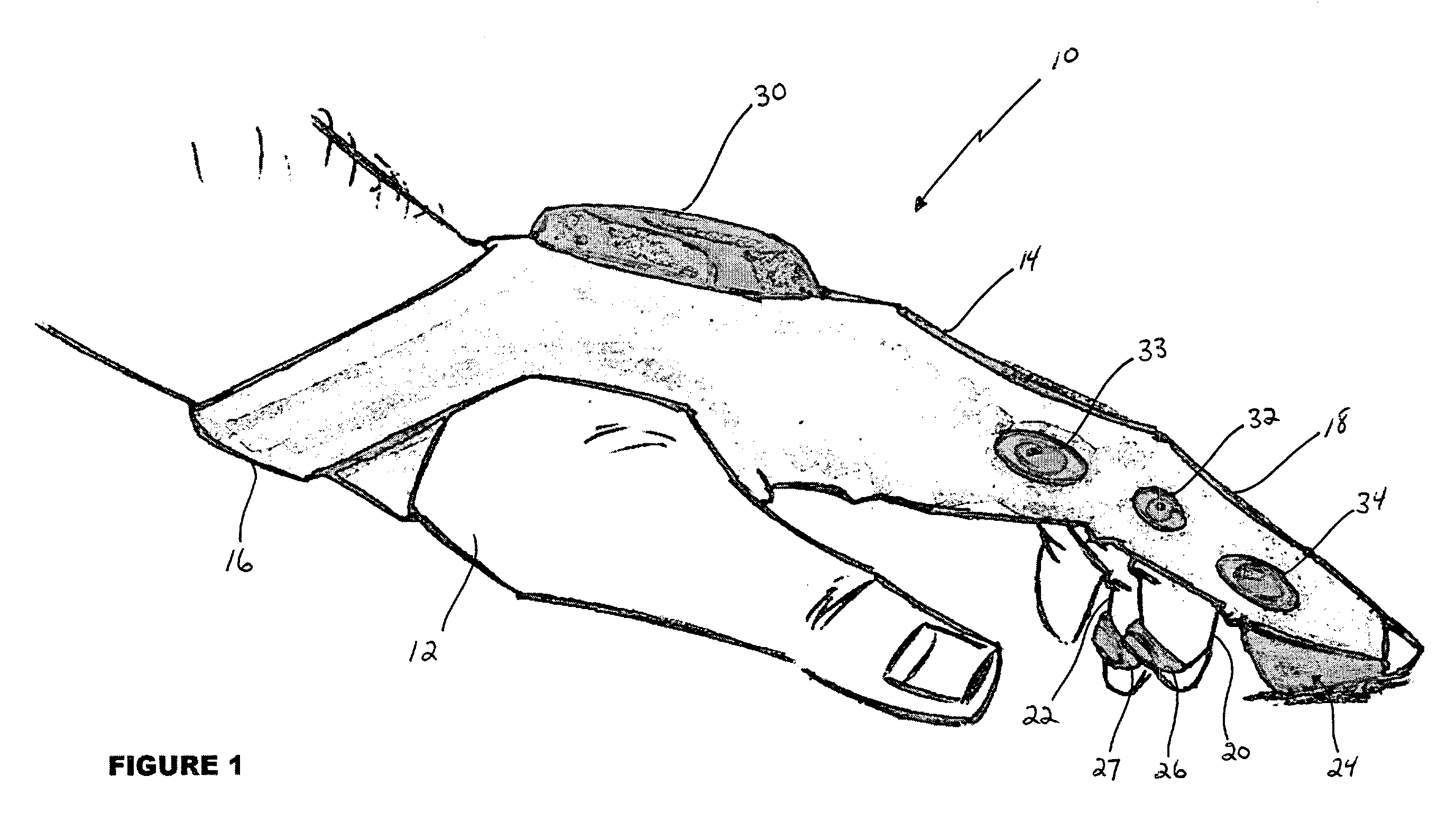
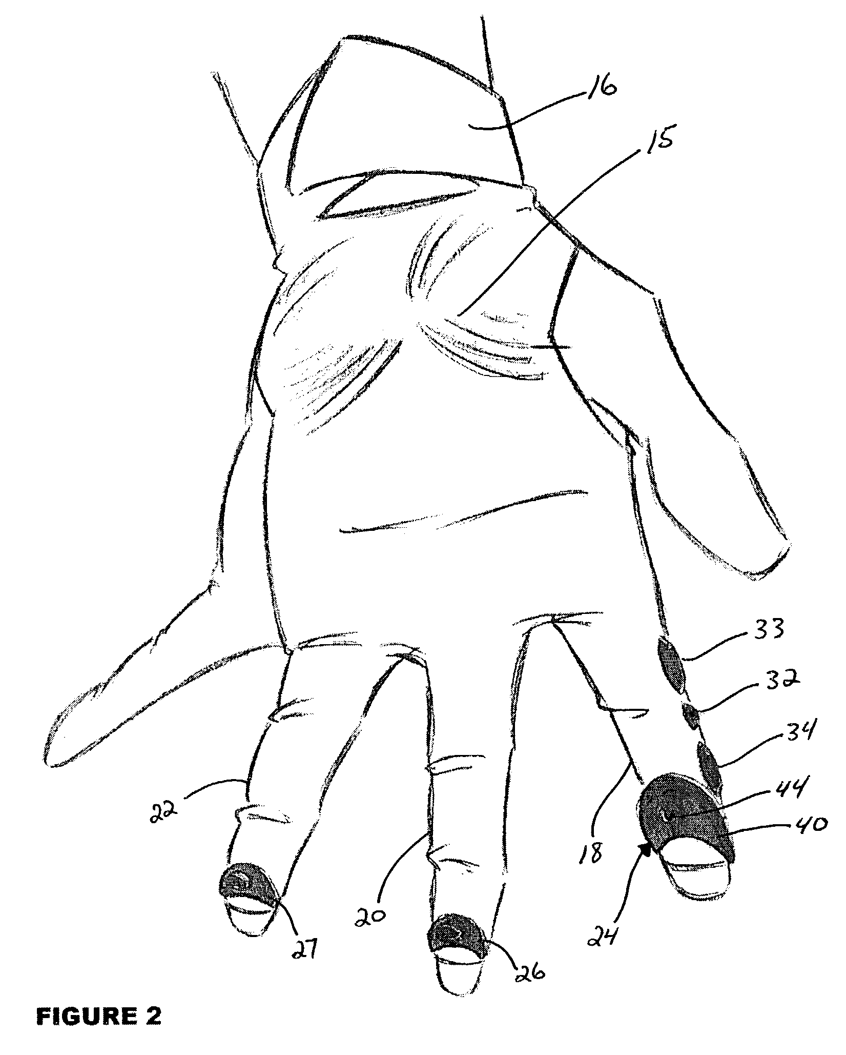
[0066]Referring to the drawings, FIG. 1 shows one preferred embodiment of the computer input device 10 of the present invention fitted on a user's left hand 12. The computer input device 10 includes a glove-like apparel 14 secured to the wrist with adjustable straps 16. Glove-like apparel 14 includes fittings for an index finger or digit 18, a middle finger 20 and a ring finger 22. A tracking device 24 is shown attached to the fitting for index finger 18 of glove 14 and pressure plates 26, 27 are shown attached to the fittings for middle finger 20 and ring finger 22, respectively. A transmitter 30 is attached to the top of glove 14 for positioning on the back of hand 12, and scroll / page buttons 32, 33, 34 are shown attached to the side of the fitting for index finger 18 where they can be easily accessed by the thumb of the user's hand 12.

[0067]It will be appreciated by the reader that the particular configuration of input device 10 shown in FIGS. 1 through 7 is for illustrative purp...


PUM


Abstract

A computer input device on a glove includes fittings for a user's fingers and adjustable straps for fastening to a user's wrist. A tracking device for controlling cursor movement on a video display is affixed to the glove for positioning next to the end of one of the user's fingers. Pressure plates for controlling the various right and left mouse “clicking” functions are affixed to the glove for positioning next to the ends of the other of the user's fingers. Scrolling / paging buttons are located on the side of the fitting fitted to the index finger for pressing by the thumb. A transmitter is affixed to the glove for receiving signals from the tracking device, the pressure plates and the scrolling / paging buttons, and transmitting those signals to a computer for controlling cursor movement in the x-y plane on a video display and for controlling the various mouse “clicking” controls, which implement the “select” function, the “drag” function, the “scroll” function, the “page” function, and so forth.

Description

CROSS REFERENCE TO RELATED APPLICATION[0001]This application is a continuation of application Ser. No. 09 / 899,277, filed Jul. 6, 2001 now abandoned.BACKGROUND OF THE INVENTION[0002]1. Field of the Invention[0003]This invention relates generally to the field of peripheral computer input devices, and more particularly to a computer mouse of the type which controls cursor movement on a video display and the various “click” controls, which implement the “select” function, the “drag” function, the “scroll” function, the “page” function, and so forth.[0004]2. Description of the Related Art[0005]A mouse is used as a computer input device to control the location of a cursor on a video display connected to the computer. Typically, cursor location is controlled by movement of the mouse across a surface. The mouse includes a tracking device for measuring the movement of the mouse across the surface. This movement is relayed to the computer where it is translated into a corresponding movement o...

Claims


Application Information

Patent Timeline
Patent Type & Authority Patents(United States)
IPC IPC(8): G09G5/08A41D19/00G06F3/033G06F3/00G06F3/01G06F3/0354
CPCG06F3/014
Inventor BAJRAMOVIC, MARK B.
Owner DEANMARK TECH
Why Eureka
Try Eureka