Handle assembly for wheeled luggage

Inactive Publication Date: 2005-03-22
OUTRIGGER
View PDF13 Cites 27 Cited by
  • Summary
  • Abstract
  • Description
  • Claims
  • Application Information

AI Technical Summary

Benefits of technology

When the handle is moved to the predetermined position of angular displacement with respect to its stowed position, the range-limiting means provides a sufficiently secure engagement to maintain the handle at this predetermined angle in resistance to those forces that are anticipated during normal towing of the case, including movement of the case across rough paving, over curbs

Problems solved by technology

It has been found that a fixed inclined handle is potentially subject to damage, i.e., bending or possibly even breaking if the case falls on the grip extended end of the handle.
Despite their obvious advantages, problems and disadvantages are left unalleviated by the improvements disclosed in these two patents.
First, since the guiding means for the handle is disposed at the same angle as the angle which the handle makes with the rear wall of the case, the length of the guiding means is limited by the angle which it makes with the rear wall of the case and th

Method used


Image

  • Handle assembly for wheeled luggage
  • Handle assembly for wheeled luggage
  • Handle assembly for wheeled luggage

Examples


Embodiment Construction

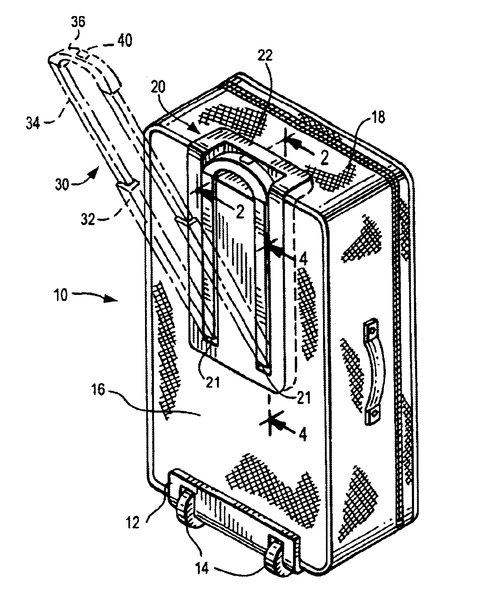
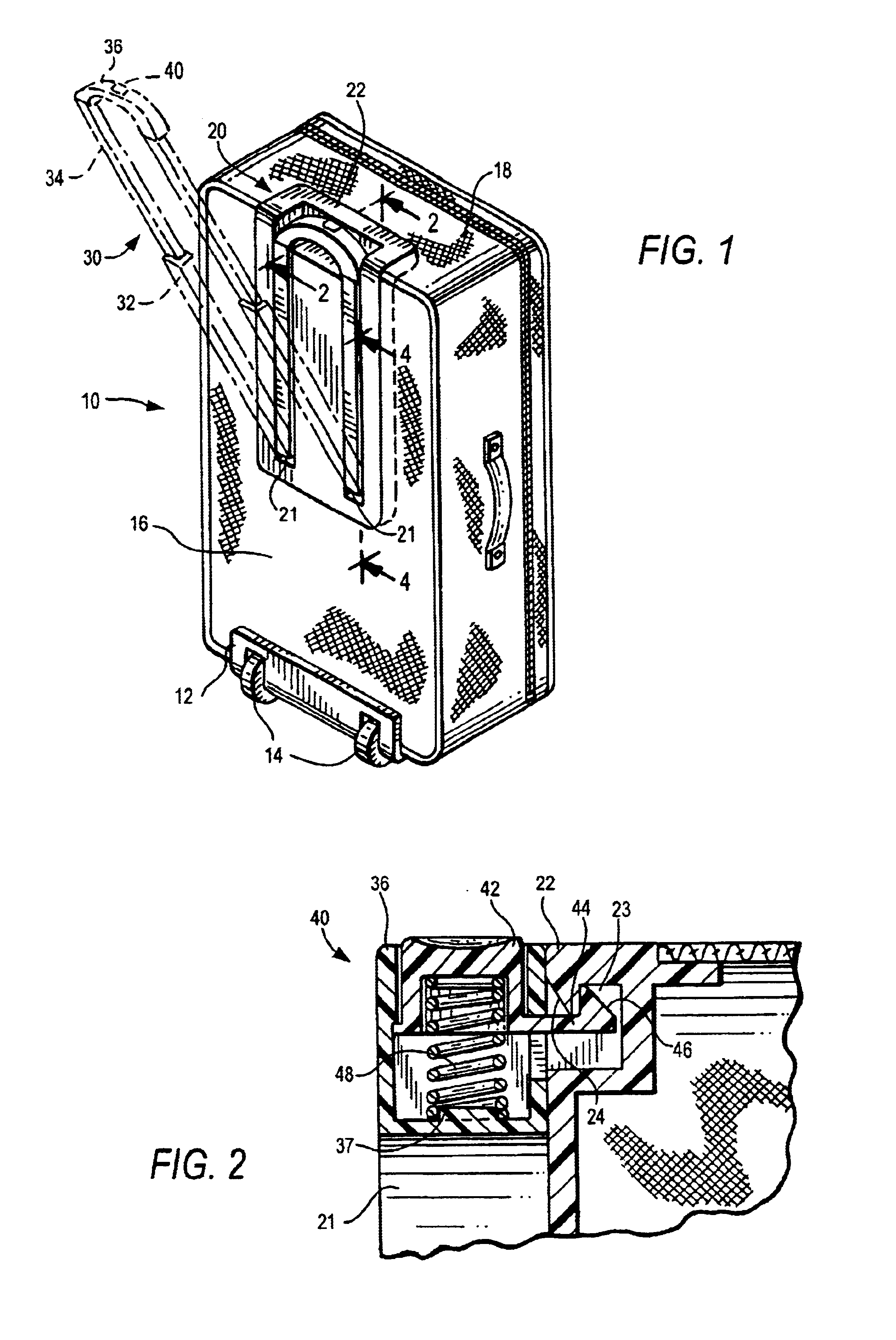
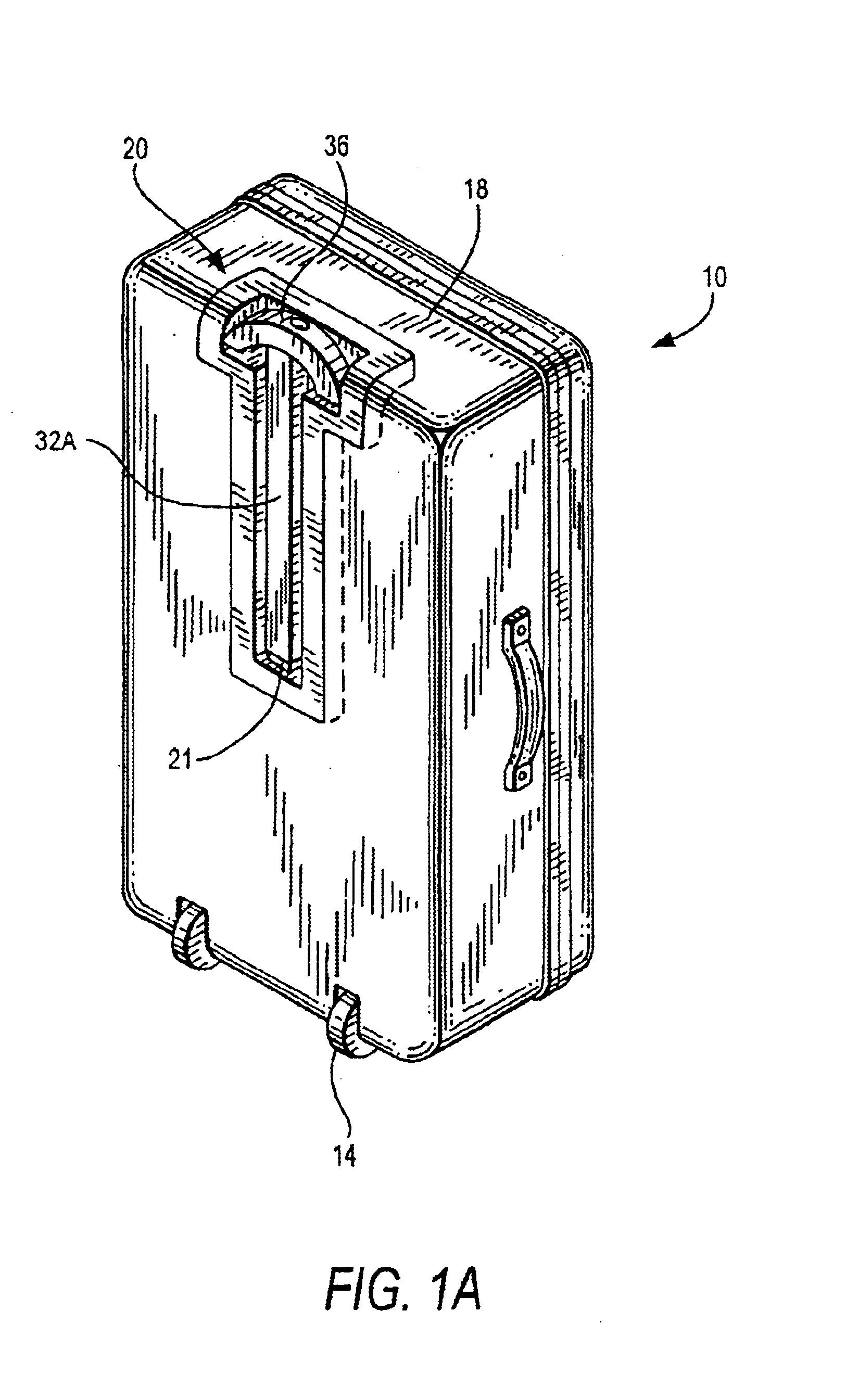
With reference to FIG. 1, there is illustrated an article of wheeled luggage or case 10, fitted with a wheel assembly 12, comprising a pair of wheels 14 attached to the junction of the back 16 and a sidewall 18 of the case. The case 10 can be fabricated from rigid materials, including polymers, metal and / or composites, all of which are well known in the art; or from fabrics such as woven nylon attached to a supporting frame work. The case can be provided with a manual carrying handle 15, on one or more of the sidewalls. The wheels 14 can be replaced by one or more rollers (not shown). The construction of the case or luggage can be in any manner known to the prior art, or that may be subsequently developed.

With continuing reference to FIG. 1, pivoting handle assembly 20 of the invention is shown secured to the back 16 and upper side wall 18 opposite the wheel assembly 12. The pivoting handle assembly 20 can be constructed from metal, or, preferably, from a combination of molded polym...


PUM


Abstract

A wheeled luggage case is provided with a universal pivoting extendable handle assembly that includes a handle that is movable from a protected retracted position in a contoured mounting plate to a fixed angularly rotated position that is about 35° from the vertical in order to minimize the vertical force on the handgrip experienced by users of wide range of heights while towing the luggage. The handle can be provided with one or a pair of telescoping legs and various handgrip configurations.

Description

FIELD OF THE INVENTIONThis invention relates to wheeled cases and luggage having an extendable handle that pivots from a stowed position parallel to the rear wall of the case to tilt the case for towing.DESCRIPTION OF THE RELATED ARTAs used herein, “towed luggage” refers to wheeled cases and luggage of various sizes and styles that are provided with a pivotally-mounted rigid handle that optionally extends and retracts, i.e., it telescopes from a position on, or adjacent to one of the walls, where the wheels or rollers are mounted at the base of, or proximate to the same wall that is adjacent to the handle.The entire disclosures of my U.S. Pat. Nos. 5,868,406 and 6,129,365 are hereby incorporated herein by reference. Also incorporated herein by reference is the disclosure of my application PCT / US01 / 47847. U.S. Pat. No. 5,868,406 generally discloses a handle inclined at an angle to the rear wall of the case when the handle is extended with respect to the case and when it is retracted ...

Claims


Application Information

Patent Timeline
IPC IPC(8): A45C13/26A45C13/00A45C13/22
CPCA45C13/262A45C13/22Y10T16/4569A45C2005/147A45C2013/265
Inventor SADOW, BERNARD D.
Owner OUTRIGGER
Why Eureka
Try Eureka