Superconductor cable

a superconductor cable and cable technology, applied in the direction of superconducting magnets/coils, superconducting devices, magnetic bodies, etc., can solve the problems of significant heat resistive and magnetic hysteresis losses, ctc technology has a difficulty developing a large conductor, and twisting transposition technology has not been used for hts superconducting tapes of thin flat shapes. to achieve the effect of reducing the strain of the conductor

Active Publication Date: 2010-04-22
MASSACHUSETTS INST OF TECH
View PDF18 Cites 28 Cited by
  • Summary
  • Abstract
  • Description
  • Claims
  • Application Information

AI Technical Summary

Benefits of technology

[0011]According to a first aspect, the invention is a superconductor cable having a plurality of flat, tape-shaped ribbon superconductor wires assembled to form a stack having a rectangular cross section. The stack has a torsional twist about a longitudinal axis of the stack. This structure is referred to herein as a “basic cable.” In a preferred embodiment, the wires are YBCO, BSCCO, or MgB2 tape conductors. It is also preferred that the stack have a substantially square cross-section. It is preferred that the twist be within the range of strain tolerances of the superconductor material, and also to minimize strain in the conductor due to bending radius of the cable. In one embodiment the superconductor wires in the twisted stack are bonded together partially or entirely. The bonding may be with electrically conducting material such as solder or with non-electrically conducting material.

Problems solved by technology

However, flux couplings created in the loop circuits among the superconducting wires generate significant heat of resistive and magnetic hysteresis losses in the superconducting wires.
However, the twisting transposition technology has not been used for HTS superconducting tapes of thin flat shapes (typically 0.1 mm thick and 4 mm wide).
The CTC technology has a difficulty developing a large conductor due to the fabrication method of the roebling.

Method used


Image

  • Superconductor cable
  • Superconductor cable
  • Superconductor cable

Examples


Embodiment Construction

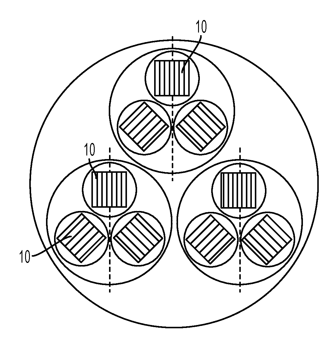
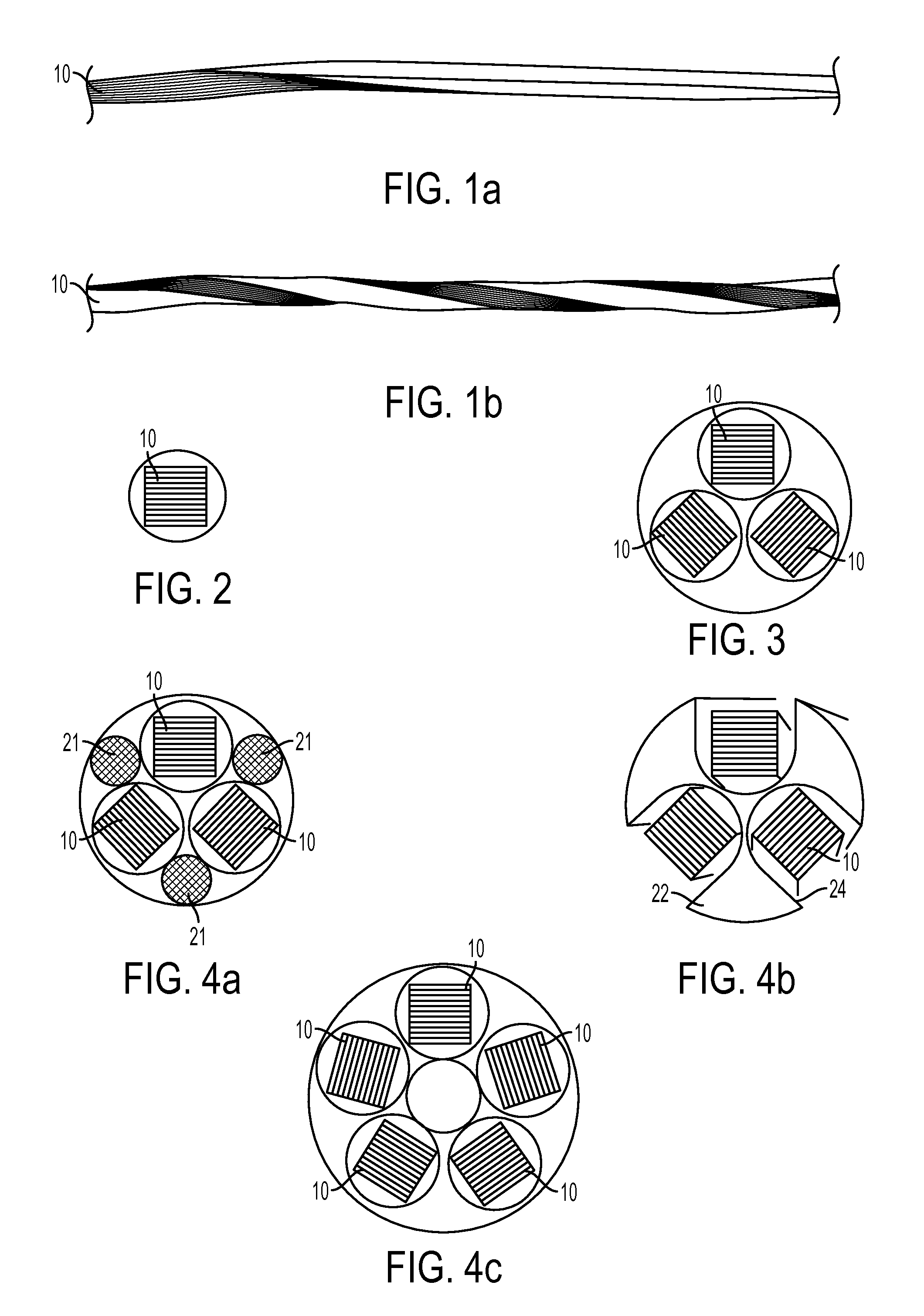
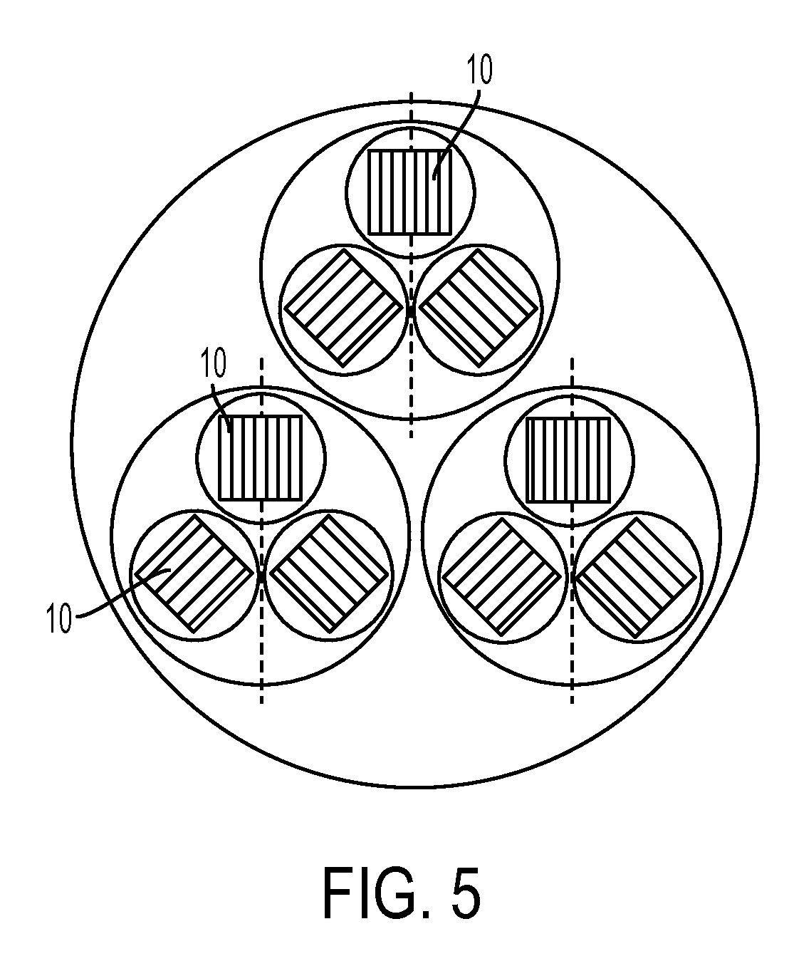
[0049]With reference first to FIG. 1(a), a multi-layer stack 10 includes a plurality of flat, tape-shaped ribbon superconducting wires that may be made from, for example, YBCO, BSCCO, or MgB2. Suitable high temperature superconducting tapes are available from American Superconductor Corporation of Westboro, Mass. and from SuperPower, Inc. of Schenectady, N.Y. as well as from other companies. After the tapes are stacked to form the stack 10, they are torsionally twisted about the longitudinal axis without an external tensile or compressive longitudinal-force, as shown in FIG. 1(b). The amount of twist is limited to the range of strain tolerances of the tape superconductors. An advantage of the innovative cable is that it makes possible that the twisting can be performed before the final wire heat treatment process to eliminate strain degradation of wire performance due to twisting such as for BSCCO tapes. The twisted multi-layered tapes may be bonded with electrical material (solderi...


PUM

PropertyMeasurementUnit
thickaaaaaaaaaa
thickaaaaaaaaaa
widthaaaaaaaaaa

Abstract

Superconductor cable having a plurality of flat, tape-shaped ribbon superconductor wires assembled to form a stack having a rectangular cross section, the stack having a twist about a longitudinal axis of the stack. Multiple superconductor cables including twisted stacked-cables of the flat-tape-shaped superconductor wires, and power cable comprising the twisted flat-tape stacked cables are disclosed. Superconducting power cable disposed within and separated from an electrical insulator with a space passing cryo-coolant between the superconducting cable and insulator is also disclosed.

Description

[0001]This application claims priority to U.S. provisional application Ser. No. 61 / 103,618 filed Oct. 8, 2008 and to U.S. provisional application Ser. No. 61 / 112,405 filed Nov. 7, 2008, the contents of both of which are incorporated herein by reference in their entirety.BACKGROUND OF THE INVENTION[0002]This invention relates to superconductor cables and more particularly to a superconductor cable made from a torsionally twisted multi-layer tape conductor stack.[0003]A significant amount of worldwide effort has been devoted over the last decade to development of High Temperature Superconductor (HTS) wires of BSCCO-2223, BSCCO-2212 and YBCO for various electronic device applications such as transformers, fault current limiters, energy storage, magnets and power transmission cables. These practical applications demand high current capacities of the HTS superconductors without accompanying AC losses or magnetic flux coupling losses.[0004]Current capacity of superconducting conductors ca...

Claims


Application Information

Patent Timeline
Patent Type & Authority Applications(United States)
IPC IPC(8): H01B12/10H01B12/16H01L39/02
CPCH01B12/02Y10T29/49014Y02E40/641Y02E40/60
Inventor TAKAYASU, MAKOTOMINERVINI, JOSEPH V.BROMBERG, LESLIE
Owner MASSACHUSETTS INST OF TECH
Why Eureka
Try Eureka