[0010]The radiopaque markers are shaped and located on the selected inflection zones such that the compressive stress exerted on the end annulus during release of the stent is shared between the markers and the inflection zones that do not carry a marker. In this way, the strain on the marker / inflection zone joints is minimised, reducing the risk of physical damage, such as breakage or deformation. This concept is applicable to any
stent design and allows for the use of only a small number of markers while the stability of the stent is secured. Keeping the number of markers at a minimum has significant advantages. First, having fewer marker / inflection zone joints reduces the danger of severed or bent markers. Self-expansible stents are extremely elastic but nevertheless not invulnerable to
distortion. Fatigue performance is of vital importance with
vascular stents, which flex with every
heartbeat. Any stress that a stent matrix suffers locally, that exceeds the maximum planned for in the Government regulatory fatigue-testing protocol can adversely affect the fatigue life of the stent. This fact emphasizes the importance of a robust
stent design, since even the slightest damage to the joints occurring during the release of the stent may shorten the service life of the stent. Furthermore, the circumference of the ring formed by the ensemble of markers in the radially compressed state of the stent is limited by the circumference of the stent tube itself. Thus, keeping the number of markers small allows for larger marker sizes and consequently an improved
visibility of the stent in the radially expanded state.
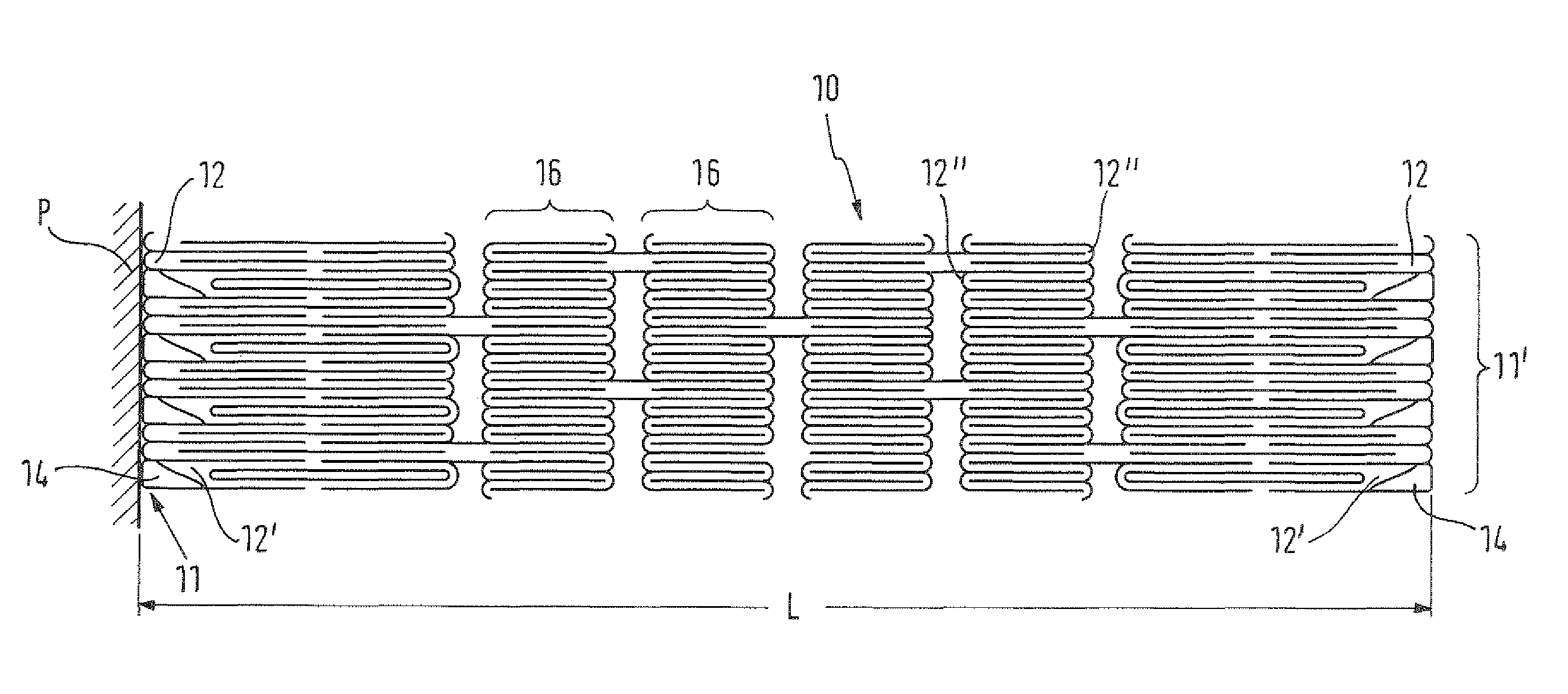
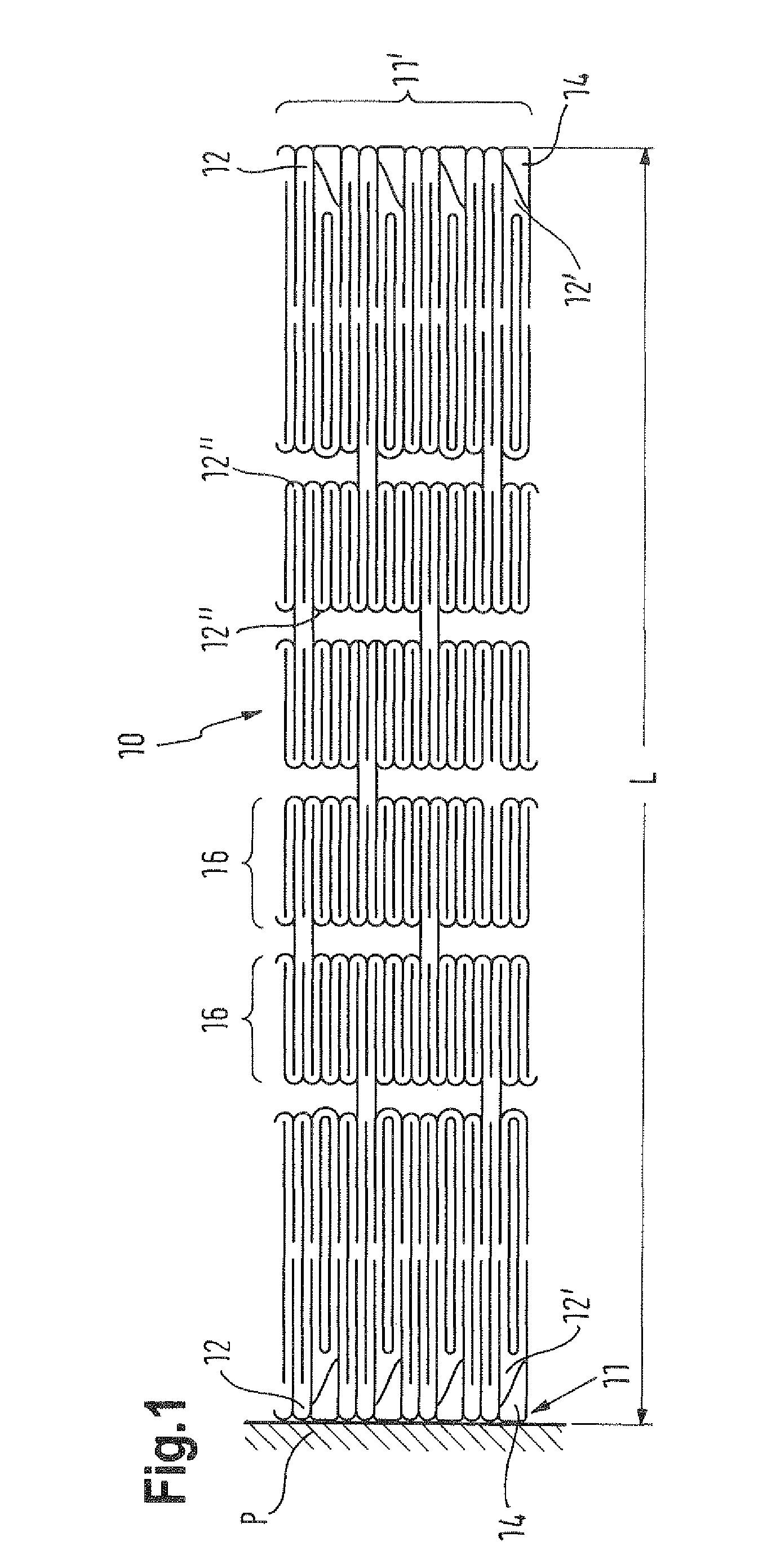
[0011]So-called “ring stents” exhibit a plurality of rings arranged along their
axial length which are interconnected between ring ends and have a plurality of inflection zones distributed in the circumference of the ring ends. In one embodiment, each of these ring ends comprises more inflection zones than the end annulus of the stent. Since, in the radially compressed state, the stent has a homogeneous circumference throughout its structure, the circumference of the end annulus of the stent will be the same as that of the ring ends, despite comprising less inflection zones. Therefore, the circumferential extent of the inflection zones that carry a marker can be increased, allowing for the attachment of larger markers, which is advantageous for reasons of
visibility as discussed above. Even more space for the markers can be created within the end annulus of the stent if the inflection zones of the end annulus of the stent that do not carry a marker have a smaller circumferential extent than the inflection zones distributed in the circumference of the ring ends. Therefore, the above arrangement facilitates a possible increase in marker size without changing the number of inflection zones of the stent rings which may affect the mechanical properties of the stent, such as stability and elasticity.
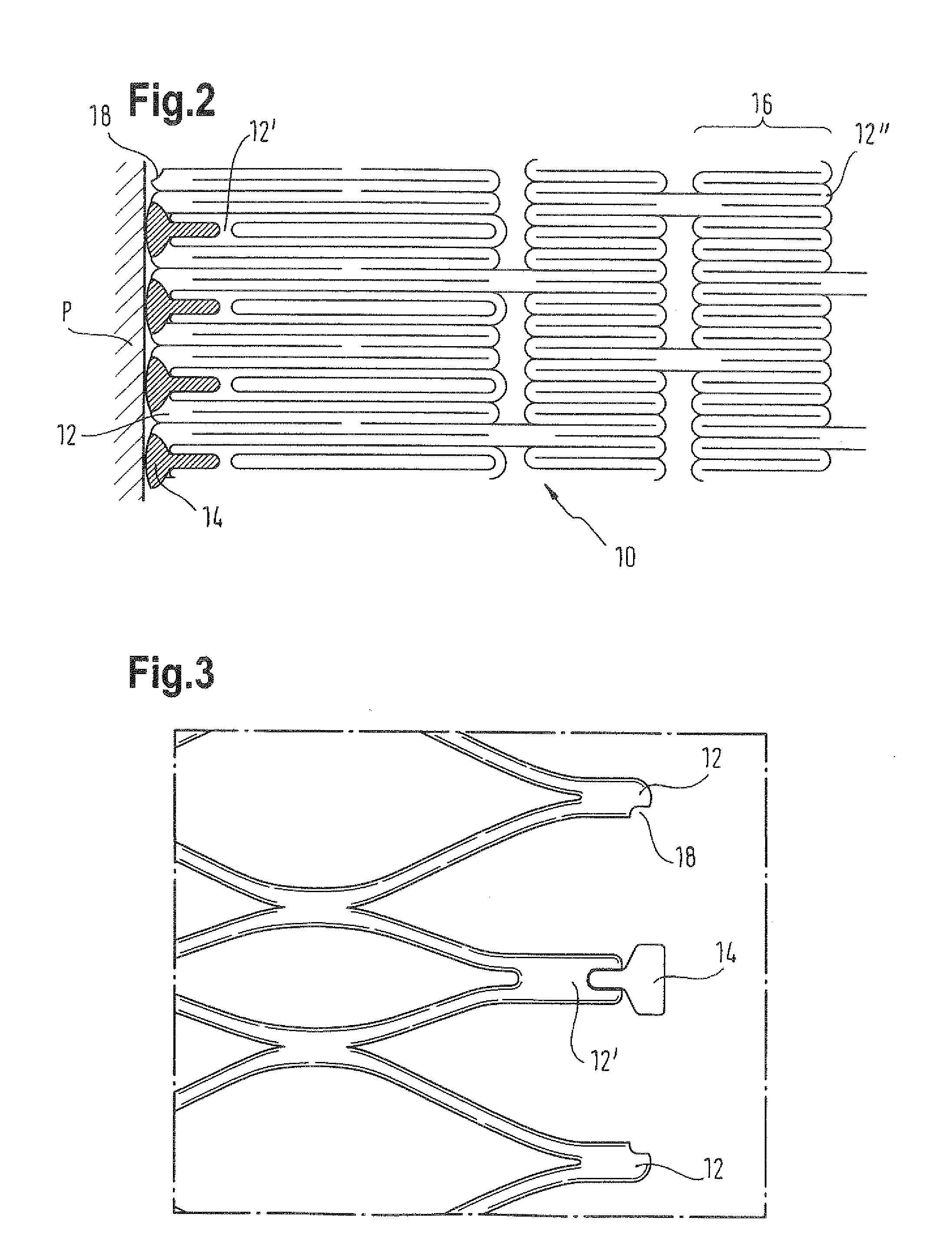
[0014]In a preferred embodiment, the inflection zones that carry a marker differ in shape, size or both shape and size from the inflection zones that do not carry a marker. The inflection zones that carry a marker may, for example, have a smaller size so as to leave more space for the attached markers or a shape particularly suited for a certain type of weld (depending on the shape and size of the marker). In one embodiment, each inflection zone is present as a stem with an
axial length parallel to the
long axis of the stent. Preferably, the inflection zone stems that carry a marker have a smaller length than the inflection, zone stems that do not carry a marker. This arrangement allows for the
accommodation of portions of the markers (or even whole markers) between the neighbouring longer inflection zones.
[0016]In a preferred embodiment, each marker subtends a larger arc of the circumference of the end annulus than each inflection zone that does not carry a marker, improving the visibility of the stent ends. In any event, the width of the marker, in the circumferential direction, will generally be as larges as, or larger than, but not smaller than, the circumferential width of the inflection zone to which the marker is attached.
[0017]A number of different materials may be used for the fabrication of the stent and the radiopaque markers. Preferably, the stent is made from a
nickel titanium shape memory alloy. Such an
alloy provides the mechanical properties necessary for reliable stent operation, namely a high degree of elasticity and
physical stability. The radiopaque markers are preferably made from
tantalum, gold, or a
ternary alloy made from
nickel,
titanium and a third, radiopaque
metal. All these metals offer a high level of radiopacity. Both the above stent and marker materials are non-toxic and provide a good biological compatibility with the
human body. For
nickel titanium stents, markers of
tantalum are of special interest because their electrochemical potentials are so similar.
[0018]In another preferred embodiment, the markers do not extend axially beyond the inflection zones which do not carry a marker, in the radially compressed state of the stent. This arrangement can be accomplished, for example, by making the inflection zones that carry a marker shorter than the ones that do not carry a marker. Preferably, during release of the stent from the
delivery system, both the markers and the inflection zones which do not carry a marker abut, or are otherwise in physical contact with, the pushing part of the
delivery system, i.e., the co-axial inner cylinder. In such a configuration, the compressive stress exerted on the end annulus during release of the stent is shared between the markers and the inflection zones without markers, minimising the risk of physical damage to the stent. A marker size large enough for excellent visibility can still be maintained by choosing a small number of inflection zones in the end annulus of the stent and by making the inflection zones that carry a marker sufficiently short.

