
Apparatus for determining free piston position and an apparatus for controlling free piston position

a technology of free piston and position, which is applied in the direction of gyroscope/turn-sensitive device, speed measurement using gyroscopic effect, galvano-magnetic hall-effect device, etc. it can solve the problem that the free piston machine inherently lacks absolute piston displacement control is virtually impossible to control the continuously variable stroke of the free piston, and cannot disclose concrete methods of how. , to achieve the effect of enhancing durability, avoiding extra cost,

Active Publication Date: 2006-07-11
GLOBAL COOLING
View PDF6 Cites 11 Cited by
  • Summary
  • Abstract
  • Description
  • Claims
  • Application Information

AI Technical Summary

Benefits of technology

This solution simplifies the system, enhances durability, reduces costs, and effectively prevents over-stroke and displacement issues in free piston machines like Stirling engines, allowing for precise control of reciprocating motion without mechanical connections.

Problems solved by technology

The free piston machine inherently lacks absolute piston displacement control of its free piston, because the free piston is not mechanically connected with a crank shaft.
However, these prior arts do not disclose concrete methods of how to detect stroke of a free piston and the average position of reciprocating motion of the free piston.
Especially, it is virtually impossible to control continuously variable stroke of the free piston.
Moreover, it is difficult to know how to detect the average position of reciprocating motion of the free piston with those prior arts.

Method used


Image

  • Apparatus for determining free piston position and an apparatus for controlling free piston position
  • Apparatus for determining free piston position and an apparatus for controlling free piston position
  • Apparatus for determining free piston position and an apparatus for controlling free piston position

Examples


Embodiment Construction

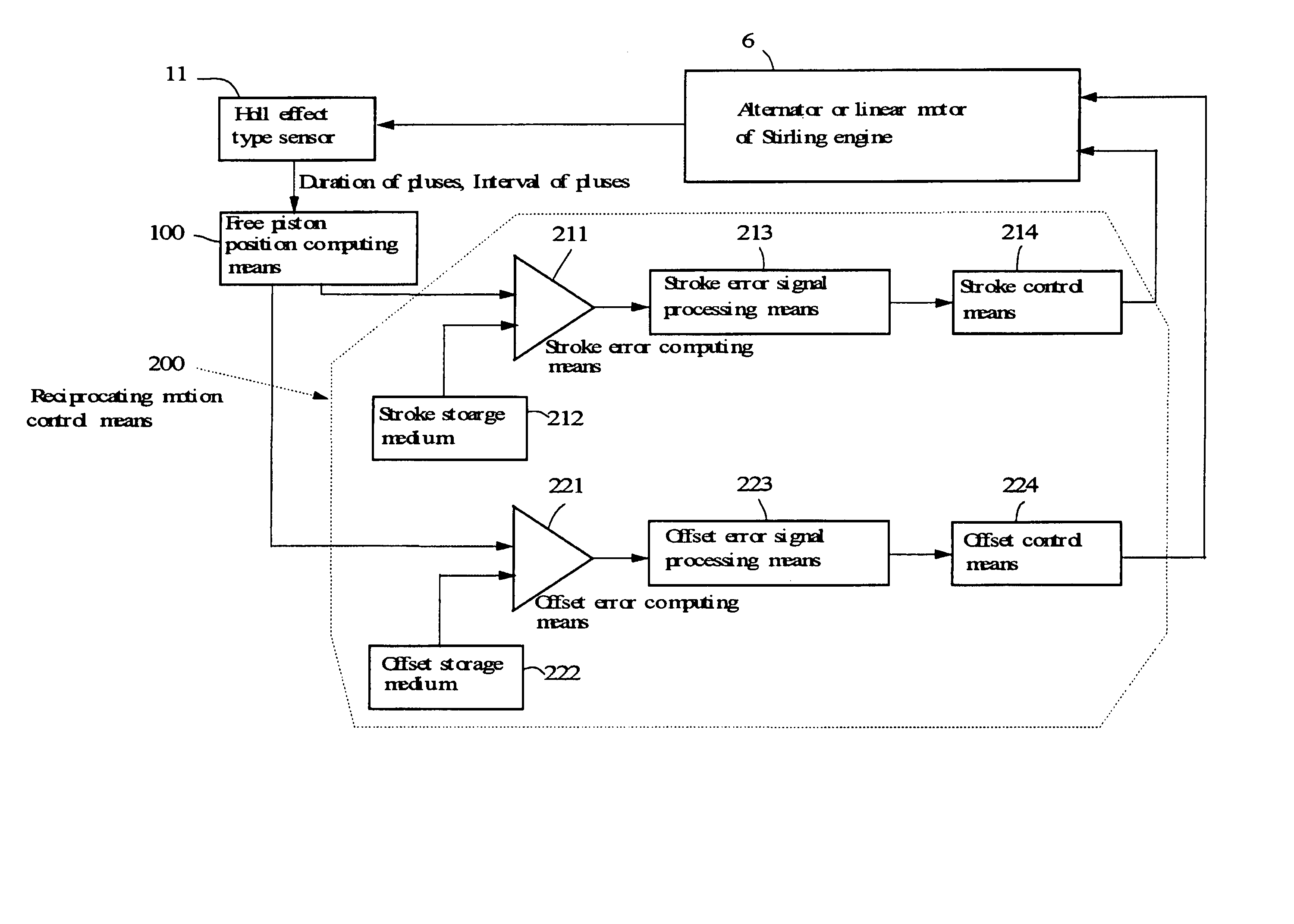
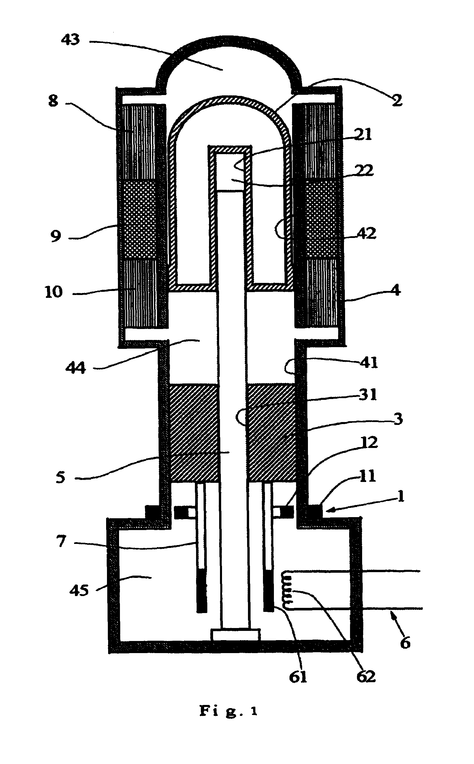
[0033]FIG. 1 discloses an outline of a free piston position determining apparatus according to the present invention, and a Stirling engine including a reciprocating motion control means. First, referring FIG. 1, the configuration and function of the Stirling engine are explained. The Stirling engine itself is well known. In the Stirling engine, a free piston 3 and a displacer 2 reciprocate in cylinder portions 41 and 42 of a case 4, and the directions of reciprocating motion of them are mutually opposite. The case 4 is made of magnetically permeable material such as austenitic stainless steel. In the centers of the free piston 3 and the displacer 2, an axis hole 31 and an axis hole 21 are formed respectively. A rod 5 fixed to the case 4 at an end is inserted in the axis holes 31 and 21. The free piston 3 and the displacer 2 reciprocate by using the rod 5 as a center axis for reciprocating motion.

[0034]A heat acceptance exchanger 8, a regenerator 9, and a heat reject exchanger 10 ar...


PUM


Abstract

An apparatus for determining position of a free piston used in such as hydraulic compressor, which has no mechanical connection with crank shaft, and an apparatus for controlling reciprocating motion of the free piston are disclosed. A free piston position determining apparatus comprises a magnetic sensor disposed in a case containing a free piston, and a magnet disposed on the free piston. The magnet sensor generates pulse train when the magnet is positioned within a pre-determined distance form the magnet sensor. Stroke of the free piston is computed based on duration of the pulse, and offset of the average piston position from designed average position is computed based on interval of the pulse.

Description

BACKGROUND OF THE INVENTION[0001]1. Field of the Invention[0002]The present invention relates to an apparatus for determining position of a free piston such as reciprocating piston in hydraulic compressor, which has no mechanical connection with driving means like a crank shaft, and an apparatus for controlling reciprocating motion of the free piston.[0003]2. Description of the Related Art[0004]A free piston machine has a reciprocating piston with no mechanical connection with a driving crank-shaft. Rather, a linear motor or an alternator is often used to drive or load a free piston in its cylinder (such as the invention disclosed in reference 1). These machines are put into practical use as gas compressors, Stirling coolers, Stirling engines, and other free piston machines.[0005]The free piston machine inherently lacks absolute piston displacement control of its free piston, because the free piston is not mechanically connected with a crank shaft. Therefore, its piston motion must ...

Claims


Application Information

Patent Timeline
Patent Type & Authority Patents(United States)
IPC IPC(8): G01B7/14
CPCF02G1/06G01D5/145F15B15/2861F02G2258/80
Inventor BERCHOWITZ, DAVID M.MASH, II, ROBERT LEE
Owner GLOBAL COOLING
Learn More