Computer enclosure with power supply bracket

Inactive Publication Date: 2006-08-08
HON HAI PRECISION IND CO LTD +1
View PDF9 Cites 16 Cited by
  • Summary
  • Abstract
  • Description
  • Claims
  • Application Information

AI Technical Summary

Benefits of technology

[0007]Accordingly, an object of the present invention is to provide a computer enclosure havi

Problems solved by technology

A screwdriver must be used to attach or detach such bracket to or from the enclosure, and it is inconvenient and laborious to manipulate the screws.
Therefore, it is similarly inconveniently and laborious to have to unscrew and remove the power supply w

Method used


Image

  • Computer enclosure with power supply bracket
  • Computer enclosure with power supply bracket
  • Computer enclosure with power supply bracket

Examples


Embodiment Construction

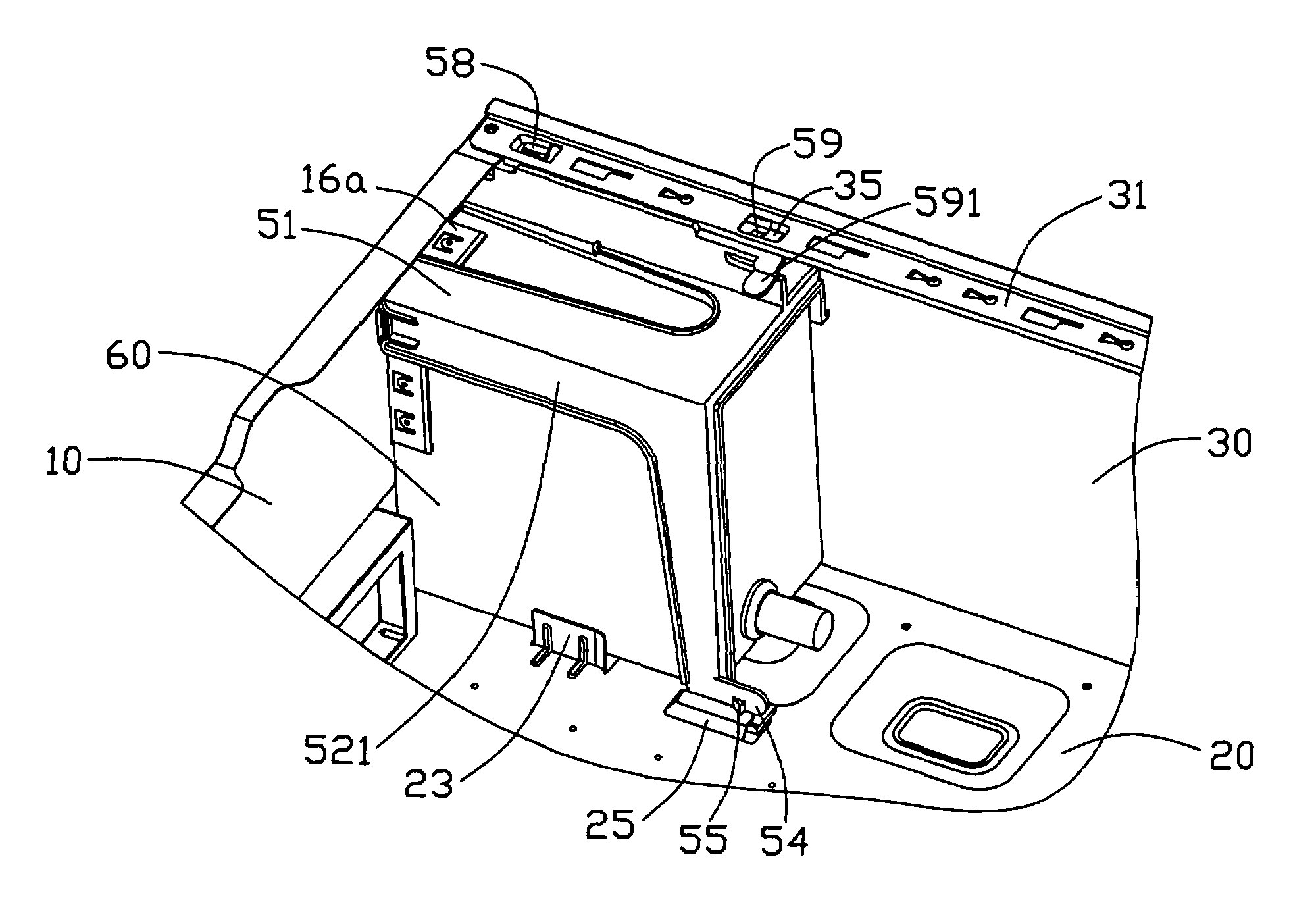
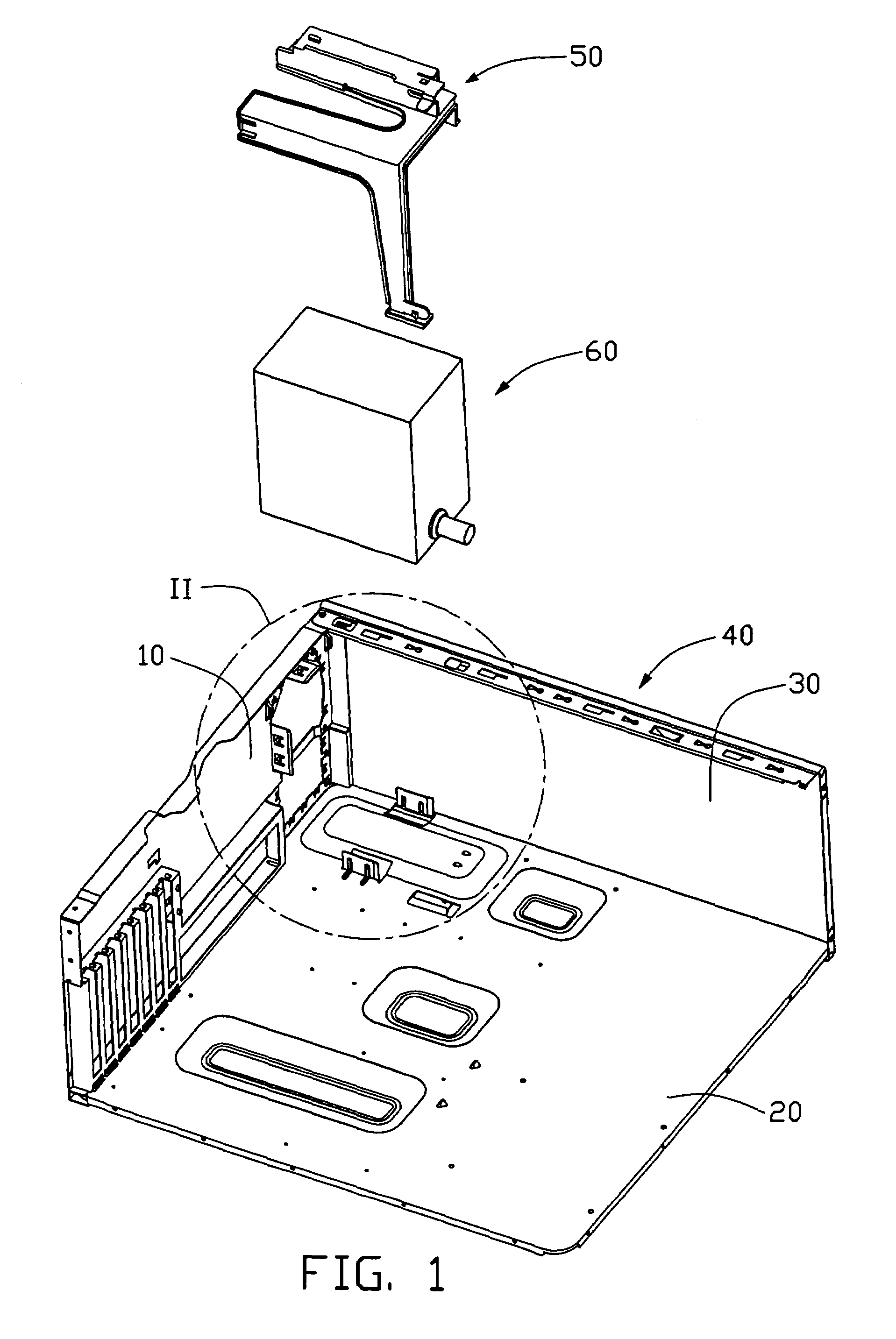
[0016]Referring to FIG. 1, a computer enclosure in accordance with the present invention comprises a cage 40 and a bracket 50. The bracket 50 is for attaching a power supply 60 to the cage 40. The cage 40 comprises a rear panel 10, a bottom panel 20, and a side panel 30.

[0017]Referring to FIG. 6, a rear wall of the power supply 60 comprises an upper fan portion (not labeled) and a lower socket portion (not labeled). A plurality of vents (not labeled) is defined in the rear wall at the fan portion.

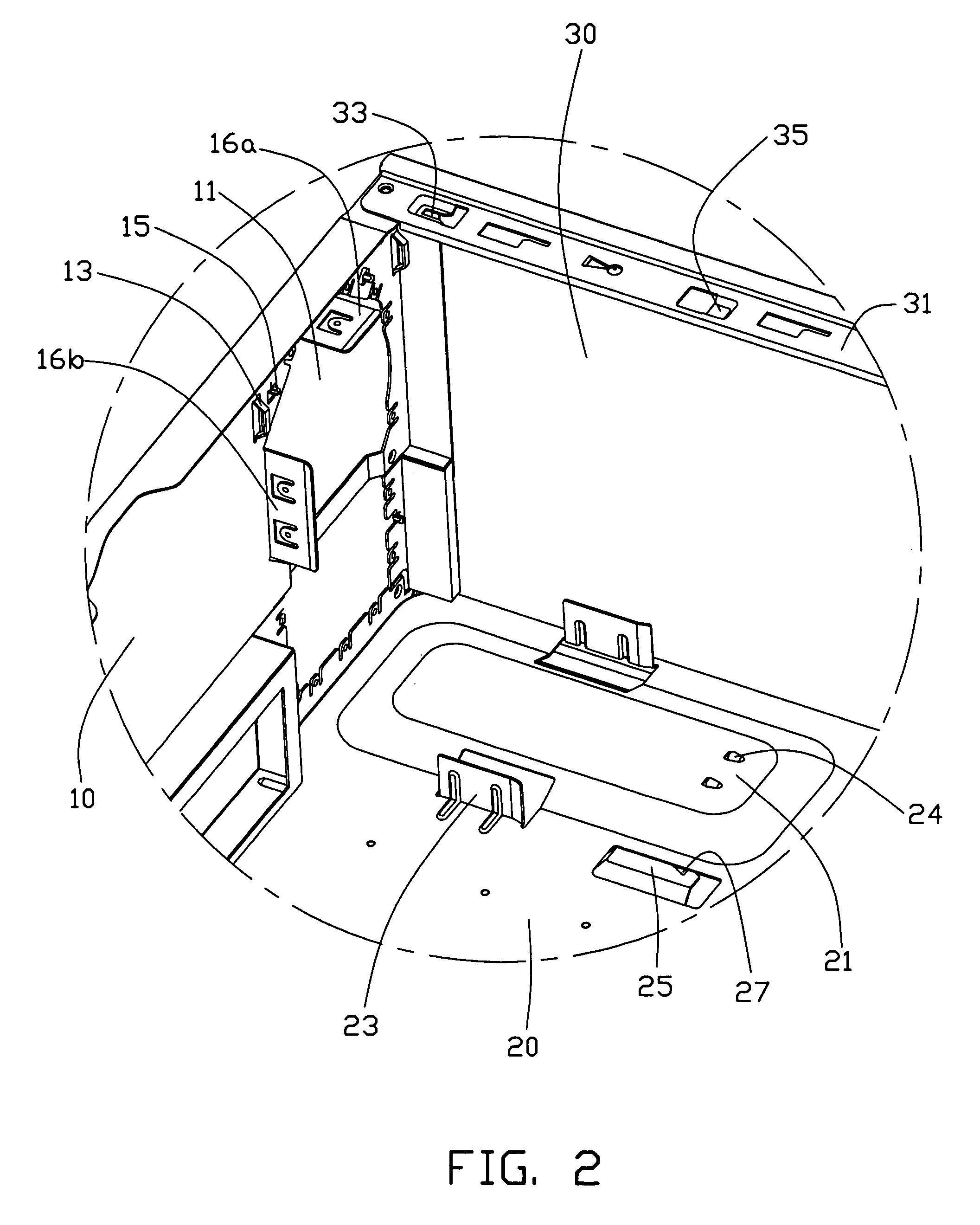
[0018]Referring also to FIG. 2, the rear panel 10 defines a pair of spaced openings 11 one above the other adjacent the side panel 30. The openings 11 provide access to the fan portion and socket portion of the fan 60. A horizontal retaining flange 16a extends inwardly from the rear panel 10 above the upper opening 11. A vertical retaining flange 16b extends inwardly from the rear panel 10 at a side of the upper opening 11. A pair of catches 13 extends inwardly from the rear panel 10 at opp...


PUM


Abstract

A computer enclosure includes a cage (40) and a bracket (50). The cage includes a rear panel (10) having a pair of catches (13), a bottom panel (20) having a bent strip (25) defining a cutout (27) therein, and side panel (30) having a latch bar (33) and a latch hook (35). The bracket includes a top wall (51) having a fastener (58) and a second stop (59), a pair side walls (52, 521) having a pair of opposite catches (56), and a rear wall frame (57). One of the side walls includes a board (53) and a first stop (55) at a bottom portion. The bracket sandwiches a power supply (60) in the cage, with the fastener and the second stop respectively engaging with the latch bar and the latch hook, the board engaging with the bent strip and the first stop engaging in the cutout.

Description

BACKGROUND OF THE INVENTION[0001]1. Field of the Invention[0002]The present invention relates to computer enclosures, and more particularly to computer enclosures having brackets for retaining power supplies therein.[0003]2. Related Art[0004]Taiwan Patent Application No. 88219428 disclose conventional computer systems in which a power supply is firstly mounted to a bracket, and then the combined bracket and power supply is attached to a rear panel of a computer enclosure with screws. A screwdriver must be used to attach or detach such bracket to or from the enclosure, and it is inconvenient and laborious to manipulate the screws. Furthermore, a typical computer enclosure with power supply is configured such that the power supply must first be removed to gain access to other components within the enclosure. Therefore, it is similarly inconveniently and laborious to have to unscrew and remove the power supply when maintenance or replacement of other components within the enclosure is ...

Claims


Application Information

Patent Timeline
IPC IPC(8): H05K5/03G06F1/18
CPCG06F1/188G06F1/184
Inventor CHEN, YUN LUNGSU, GANG
Owner HON HAI PRECISION IND CO LTD
Why Eureka
Try Eureka