System and methods for providing a driving circuit for active matrix type displays

a driving circuit and active matrix technology, applied in static indicating devices, instruments, electroluminescent light sources, etc., can solve problems such as irregular luminance, and achieve the effect of increasing power consumption and cos

Inactive Publication Date: 2006-08-15
SEIKO EPSON CORP
View PDF28 Cites 78 Cited by
  • Summary
  • Abstract
  • Description
  • Claims
  • Application Information

AI Technical Summary

Benefits of technology

[0017]Accordingly, an object of the present invention is to provide a driving circuit for an active matrix type display capable of applying reverse bias to an electro-optical element such as an organic el

Problems solved by technology

Accordingly, even if the same voltage is applied to the gates of transistors, a current having a given

Method used


Image

  • System and methods for providing a driving circuit for active matrix type displays
  • System and methods for providing a driving circuit for active matrix type displays
  • System and methods for providing a driving circuit for active matrix type displays

Examples


Embodiment Construction

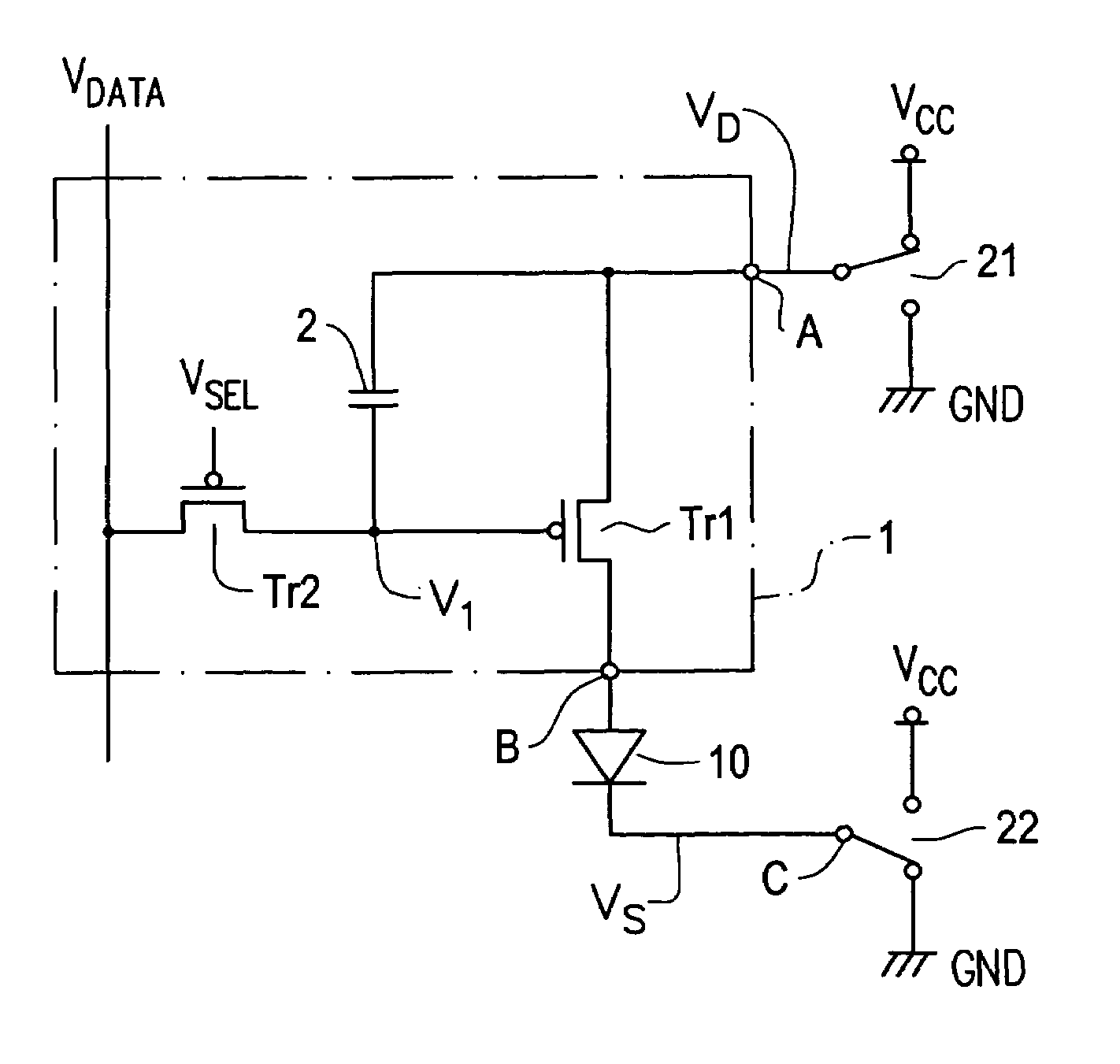
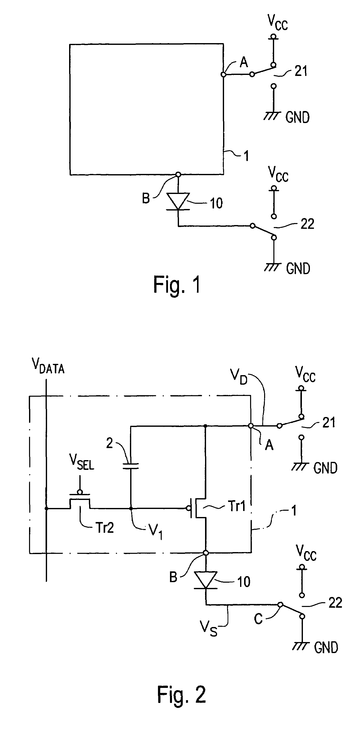
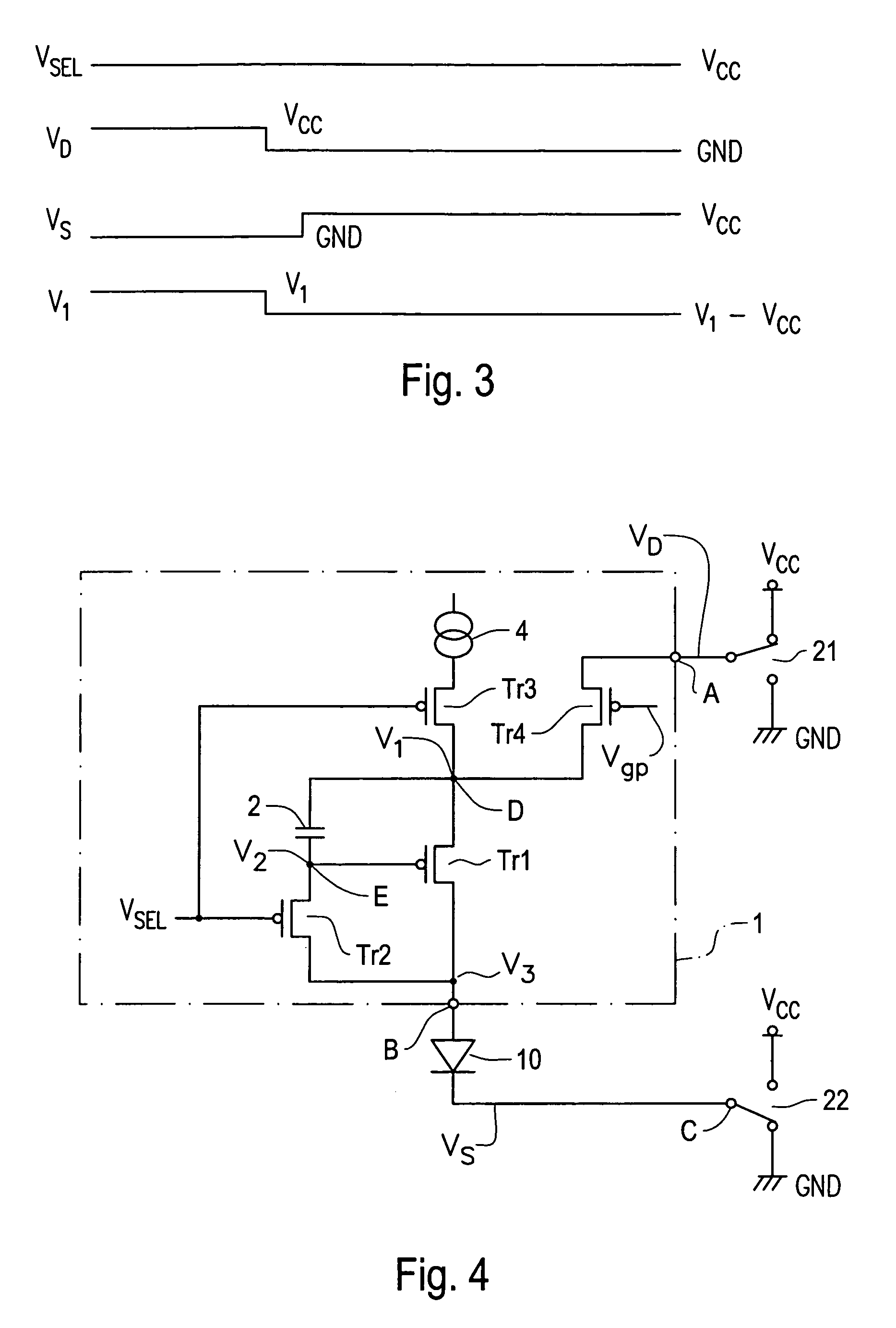
[0049]Next, an embodiment of the present invention will be described with reference to the drawings. Note that, in the respective drawings referred to in the following description, the same components as those in other drawings are denoted by the same reference numerals.

[0050]FIG. 1 is an exemplary block diagram showing a driving circuit for an active matrix type display using an organic electroluminescence element according to the present invention. As shown in the figure, the driving circuit 1 for the organic electroluminescence element of the embodiment has a first terminal A. The first terminal A can be electrically connected to any one of a first power supply line for supplying a first potential (Vcc) and a second power supply line for supplying a second potential GND lower than the first potential by a switch 21.

[0051]Further, the driving circuit 1 for the organic electroluminescence element can include a second terminal B. The second terminal B is electrically connected to a ...


PUM


Abstract

The present invention provides an organic electroluminescence element driving circuit that is capable of realizing application of reverse bias without increasing power consumption and cost. The connected relationship between a power supply potential Vcc and the GRD is changed by manipulating switches. With this arrangement, application of reverse bias to an organic electroluminescence element can be realized without newly preparing additional power supplies such as a negative power supply, and the like, whereby the life of an organic electroluminescence element can be increased.

Description

[0001]The present application is a divisional of U.S. application Ser. No. 09 / 956,030 filed on Sep. 20, 2001, which is now U.S. Pat. No. 6,750,832, which claims priority from the following Japanese Patent Applications No. 2000-285329 filed Sep. 20, 2000 and 2001-254850 filed Aug. 24, 2001, and is hereby incorporated by reference in its entirety.BACKGROUND OF THE INVENTION[0002]1. Field of Invention[0003]The invention relates to a driving circuit for an active matrix type display using an electro-optical element, such as an organic electroluminescence element (hereinafter referred to as “organic electroluminescence element”), and the like. The invention further relates to a driving method of electronic device and an electronic apparatus, and to the electronic device. More particularly, the present invention relates to a driving circuit having a function for applying reverse bias to an electro-optical element to suppress the deterioration thereof, to a driving method of electronic dev...

Claims


Application Information

Patent Timeline
IPC IPC(8): G09G3/10G09G3/20H05B44/00G09G3/30G09G3/32H01L51/50
CPCG09G3/3233G09G3/325G09G2300/0819G09G2300/0842G09G2320/043G09G2300/0866G09G2310/0251G09G2310/0256G09G2310/0262G09G2300/0861G09G3/30
Inventor KASAI, TOSHIYUKI
Owner SEIKO EPSON CORP
Why Eureka
Try Eureka