Rotary electric machine for vehicles

a technology of electric machines and vehicles, applied in windings, dynamo-electric components, magnetic circuit shapes/forms/construction, etc., can solve the problems of inconvenient welding of welding techniques, difficult electrical connection between leads of stator windings and rectifiers, and inability to meet the requirements of tig welding

Inactive Publication Date: 2007-01-11
DENSO CORP
View PDF26 Cites 47 Cited by
  • Summary
  • Abstract
  • Description
  • Claims
  • Application Information

AI Technical Summary

Benefits of technology

[0010] The present invention has been made in view of the problems described above, and has an object of providing a vehicular rotary electric machine, which facilitates assembling of parts, has good serviceability, and can improve vibration resistance without significantly increasing the cost.
[0011] As one aspect of the present invention, there is provided a rotary electric machine comprising a rotor rotatably driven; and a stator having a stator iron core disposed to face the rotor and stator windings mounted at the stator iron core, the stator windings being composed of a plurality of electric conductors made from aluminum and copper. Thus, only the portions confronting strong vibration and requiring vibration resistance, can be constituted of copper conductors, and the other portions can be constituted of aluminum conductors. Thus, the entire vibration resistance of the stator windings can be improved without significantly increasing the cost.
[0012] It is preferred that the rotary electric machine comprises a rectifier electrically rectifying an alternating current induced in the stator windings and outputted therefrom, wherein the plurality of stator windings include windings connected to the rectifier and the windings connected to the rectifier is at least made from the copper. Hence, this arrangement enables the use of TIG welding or the like which has been historically used for the connection between stator windings and a rectifier. In other words, owing to the arrangement, assembling of parts in overseas manufacturing bases or in small-scale domestic production lines can be realized. At the same time, owing to the availability of soldering, serviceability in the market can be improved.

Problems solved by technology

On the other hand, when stator windings are constituted of conductors made from aluminum, electrical connection between leads of the stator windings and a terminal of a rectifier is difficult to achieve.
This is because aluminum structuring the conductors of the stator windings and copper structuring the terminal of the rectifier are dissimilar metals having different melting points, and thus are not suitable for TIG welding or the like.
From the technical point of view, aluminum and copper can be joined, for example, by ultrasonic welding and friction welding, however, such welding techniques require dedicated equipment.
This raises a problem in that assembling of parts cannot be readily carried out in overseas manufacturing bases or in small-scale domestic production lines.
Further, since soldering is difficult between the copper conductors of the stator windings and the aluminum terminal of the rectifier, another problem is raised in that serviceability, such as repair in the market and replacement of parts, is considerably deteriorated.
In addition, rotary electric machines mounted on an engine are under extreme vibration conditions.
In this regard, when the stator windings including the leads are made of aluminum whose mechanical strength is inherently low, the leads which are run relatively longer distance than other conductors of the stator windings present a problematic deterioration in vibration resistance.

Method used


Image

  • Rotary electric machine for vehicles
  • Rotary electric machine for vehicles
  • Rotary electric machine for vehicles

Examples


Embodiment Construction

[0031] With reference to the accompanying drawings, hereinafter is described in detail an embodiment of a vehicular AC generator (alternator) to which the vehicular rotary electric machine according to the present invention has been applied.

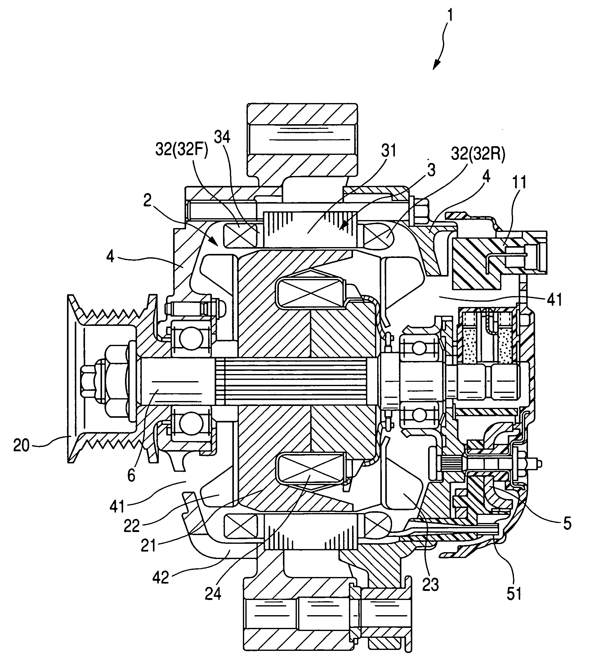
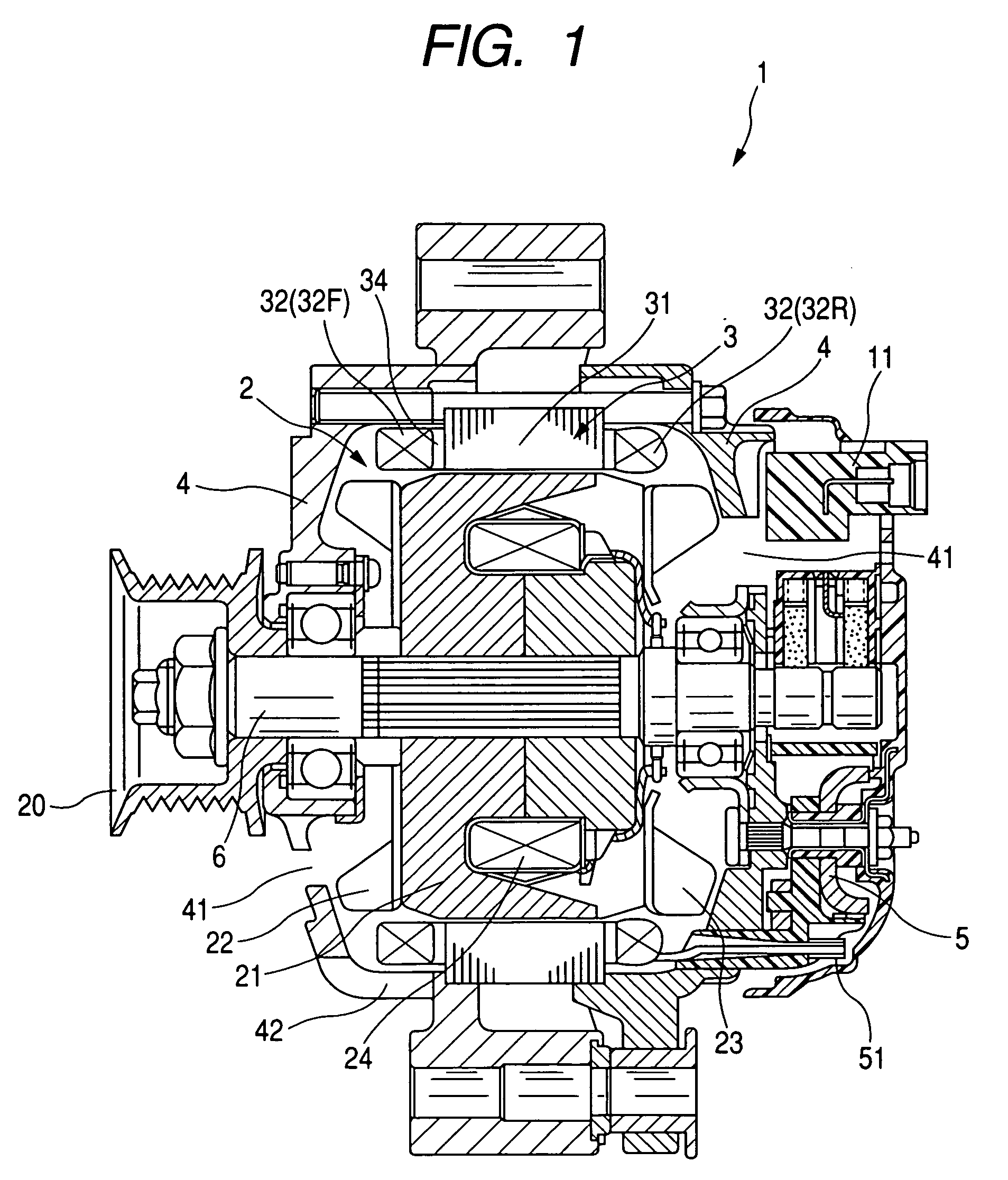
[0032]FIG. 1 shows a cross section of a vehicular AC generator 1 according to an embodiment of the present invention. As shown in FIG. 1, the vehicular AC generator 1 of the present embodiment includes a rotor 2, a stator 3, a frame 4, a rectifier 5 and a regulator 11. The vehicular AC generator 1 also includes a pulley 20 for receiving torque from an engine (not shown).

[0033] The pulley 20 is fixed to a shaft 6 together with the rotor 2. The rotor 2 is provided with a pair of Lundell type iron cores 21 and a field coil 24, and rotated / driven by the engine. This Lundell type iron cores 21 are provided, at axial end faces thereof, with respective cooling fans 22 and 23. The cooling fans 22 and 23 take cooling air into the inside from an opening ...


PUM


Abstract

A rotary electric machine, such as a vehicular AC generator, comprises a rotor rotatably driven; and a stator having a stator iron core disposed to face the rotor and stator windings mounted at the stator iron core, the stator windings being composed of a plurality of electric conductors made from aluminum and copper. For example, the plurality of stator windings are different in materials from each other winding by winding, the materials being either the aluminum or the copper. Alternatively, the plurality of stator windings include windings each being made, part by part, from different materials, the different materials being the aluminum and the copper.

Description

CROSS-REFERENCE TO RELATED APPLICATION [0001] This application is based on and claims the benefit of priority from earlier Japanese Patent Application No. 2005-198757 filed on Jul. 7, 2005, the description of which is incorporated herein by reference. BACKGROUND OF THE INVENTION [0002] 1. Technical Field of the Invention [0003] The present invention relates to rotary electric machines for vehicles, such as automobiles and trucks. [0004] 2. Related Art [0005] Segment type coils wound about or embedded in a stator are known well in the art. Such coils wound about or embedded in a stator (hereinafter referred to as “stator windings”) typically consist of a number of U-shaped electrical conductors. Segment type stator windings are typically made of copper, however, as disclosed in Japanese Unexamined Patent Application Publication No. 11-191946, windings made of aluminum are also known. Aluminum conductors can provide such merits as reducing weight, and preventing corrosion that may be ...

Claims


Application Information

Patent Timeline
Patent Type & Authority Applications(United States)
IPC IPC(8): H02K3/00
CPCH02K3/02
Inventor MATSUBARA, SHINICHI
Owner DENSO CORP
Why Eureka
Try Eureka