
Master cylinder lever for a hydraulic disc brake having favorable handle pivot geometry

a technology of hydraulic disc brakes and levers, applied in the direction of cycle brakes, cycle equipment, vehicle components, etc., can solve the problems of unfavorable geometry, loss of mechanical advantage, and failure to recognize the favorable geometry of motorcycle levers, so as to facilitate a more efficient lever actuation stroke and enhance product safety. , the effect of increasing mechanical advantag

Active Publication Date: 2007-04-17
SRAM CORPORATION
View PDF29 Cites 41 Cited by
  • Summary
  • Abstract
  • Description
  • Claims
  • Application Information

AI Technical Summary

Benefits of technology

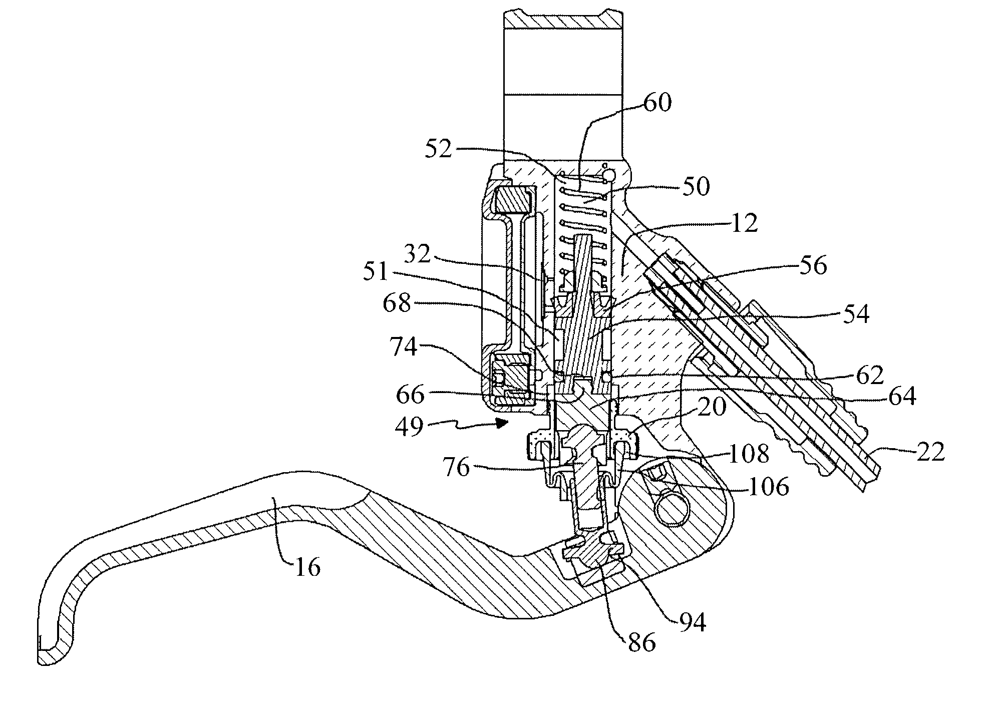
[0006]A first aspect of the present invention is a bicycle hydraulic disc brake master cylinder. The bicycle hydraulic disc brake master cylinder includes a housing having a bar clamp at one end configured for fastening the housing to a bicycle handlebar, the bar clamp receiving the handlebar along a clamp axis. A piston train resides within the housing and is operatively associated with a fluid cylinder for movement within the fluid cylinder from a non-actuated position to a fully-actuated position by action of a drive force on the piston train. A handle is pivotably connected to the housing to pivot about a pivot axis in operative association with the piston train to impart the drive force on the piston train. The handle has a select length from the pivot axis to a distal end and has a finger receptacle configured to receive at least one finger of a user defining an effective force point at a first select distance from the distal end of the handle. A select ideal finger actuation path for the at least one finger of a user begins at a start point at the effective finger force point with the handle at an engagement point where the handle begins to drive the piston train against operative fluid resistance and extends along a line from the start point at a select angle relative to the clamp axis. A pivotable connection between the handle and the housing is located on the housing relative to the clamp axis so that with the handle actuated by a force applied to the effective finger force point along the select ideal finger actuation path, a mechanical advantage to a user resulting from the handle actuation does not diminish more than 3% as the handle is pivoted between the engagement point and a fully-actuated position. The select angle may be greater than 90° and preferably is about 96°. The finger receptacle is preferably configured to receive an index finger of a user during master cylinder actuation and the effective finger force point is at an axial center of the index finger received in the receptacle. In a highly preferred embodiment, the mechanical advantage to a user resulting from the handle actuation does not diminish over 1% as the handle is pivoted between the engagement point and the fully-actuated position. Preferably, the pivotal connection is located on the housing relative to the clamp axis so that there is substantially no net loss of mechanical advantage as the handle is pivoted between the engagement point and the fully-actuated position. The select length of the handle is preferably 120 mm or less and the first select distance is preferably about 30 mm.
[0010]The present invention provides a lever pivot geometry which allows a typical user to enjoy an increase in mechanical advantage over at least a part of a hydraulic lever actuation stroke. Not only does this facilitate a more efficient lever actuation stroke, it enhances product safety by minimizing fatigue to a user's hands. The location of the pivot axis also allows a hydraulic lever to safely accommodate smaller hands having a shorter reach, while still providing the advantage of an increase in mechanical advantage over at least a portion of the lever path. These significant advantages are provided without increasing lever cost or manufacturing complexity over that of conventional lever designs having a decreasing mechanical advantage over the entire lever path.

Problems solved by technology

A known problem with bicycle hydraulic disc brake master cylinders stems their evolution from motorcycle hydraulic disc brake master cylinder levers.
Heretofore, the manufactures of hydraulic brake levers for bicycles failed to recognize that motorcycle lever geometry is not favorable.
The reason the motorcycle levers tend to result in a loss of mechanical advantage as the lever is applied is primarily because the pivot point of the lever is located relatively far away from an axis of a clamp securing the lever to the motorcycle handlebar.
Known prior art bicycle hydraulic disc levers incorporate this unfavorable geometry.
It should be further noted that the lever geometry with the pivot point 50 mm or greater from the clamp axis cannot readily be adapted to provide an increasing mechanical advantage over the lever stroke because lever movement is necessary before the lever reaches the engagement point and thus, the start position of the lever must typically be at least 5 mm beyond the engagement point to accommodate this “dead-band.” With the Brand A lever, having the most favorable pivot spacing at 50 mm, this would require an initial lever reach of at least 55 mm, which would be uncomfortable for all users except those having the largest hands.
Known levers having their pivot points 50 mm or greater from the clamp axis significantly rob braking power from such users.

Method used


Image

  • Master cylinder lever for a hydraulic disc brake having favorable handle pivot geometry
  • Master cylinder lever for a hydraulic disc brake having favorable handle pivot geometry
  • Master cylinder lever for a hydraulic disc brake having favorable handle pivot geometry

Examples


first embodiment

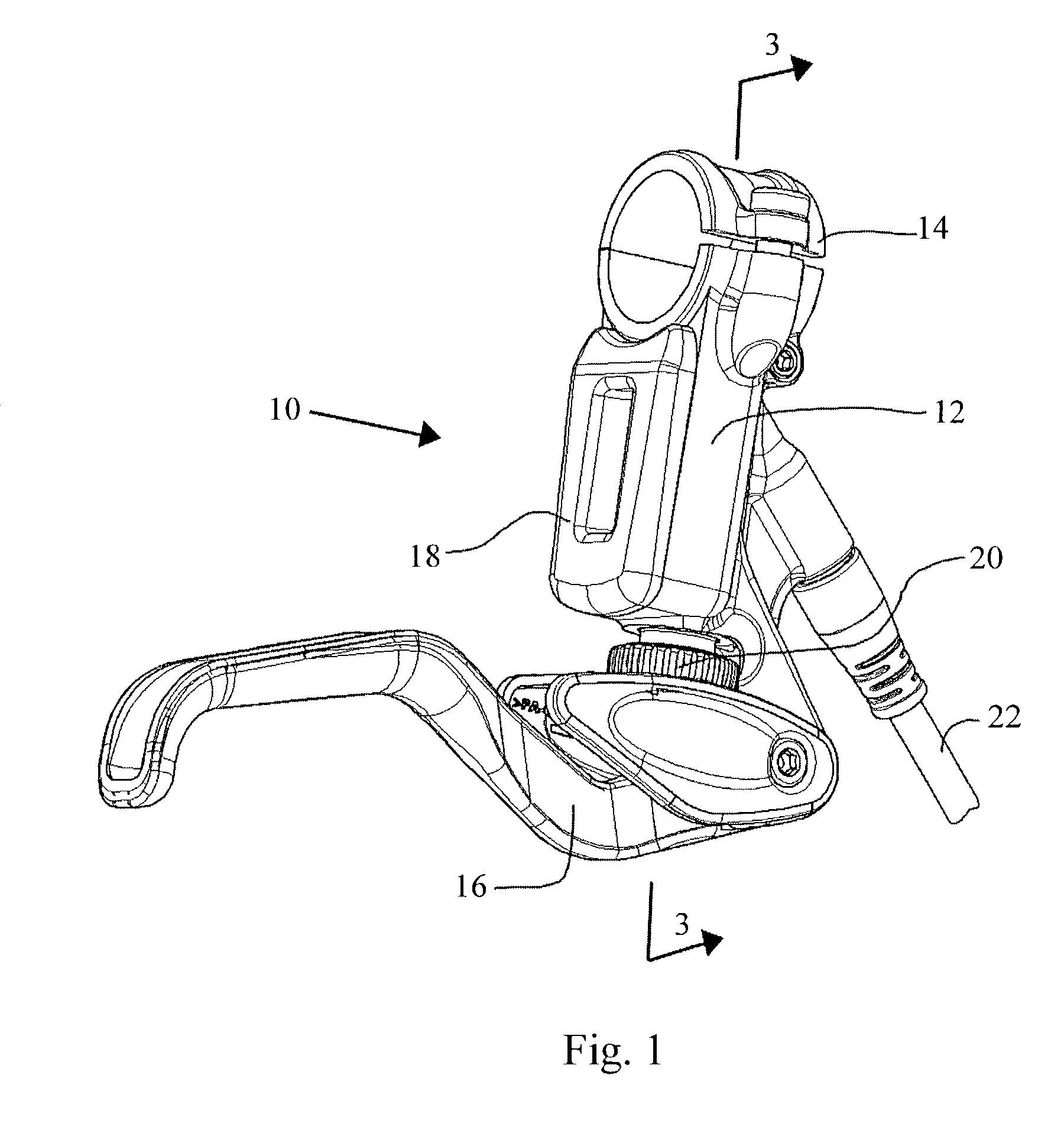
[0037]master cylinder lever assembly 10 is illustrated in a perspective view in FIG. 1. The master cylinder lever assembly consists generally of a cylinder housing 12 having a bar clamp 14 at one end and a lever handle 16 pivotably attached at an opposite end. Also seen in FIG. 1 is a reservoir cover 18 which covers a “backpack” reservoir which will be described in greater detail below. Also visible in FIG. 1 is a contact point adjustment knob 20 which is also described in greater detail below. The master cylinder housing 12 is hydraulically connected to a slave cylinder which operates a hydraulic caliper (not shown) by hydraulic line 22.

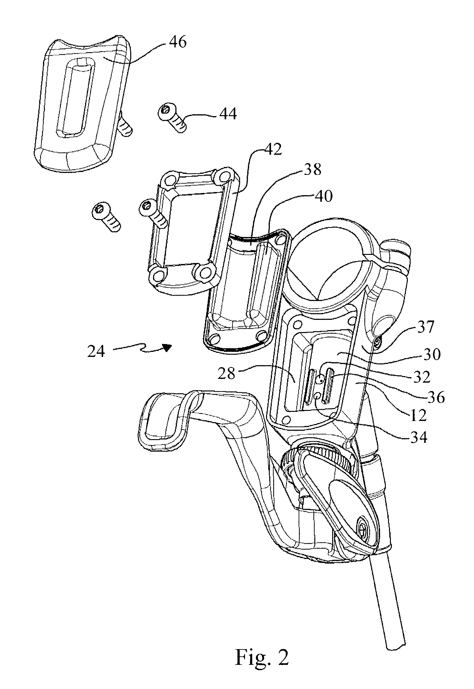
[0038]FIG. 2 is an exploded view of the “backpack” reservoir 24 of the master cylinder lever of FIG. 1. The backpack reservoir consists of a reservoir chamber 28 defined in a rear facing portion of the master cylinder housing 12. A cylinder wall 30 defining in part the cylinder of the master cylinder housing 12 extends into the reservoir chamber 28 ...

second embodiment

[0055]the hydraulic cylinder lever of FIG. 12 also includes a structure for compensating for movement of the push rod during dead-band adjustment to maintain the lever 206 in a select rest position. The threads between the threaded portion 236 of the push rod and the threaded bore 268 of the cross dowel 266 are configured to counteract pivoting of the handle that would otherwise occur about the lever pivot assembly 110 when the push rod 234 is moved by movement of the threaded insert 244. In other words, as the threaded insert 244 is advanced toward the second end of the cylinder, which necessarily causes the advancement of the push rod 234 toward the second end of the cylinder and which would normally cause the lever handle 206 to pivot upward, the threaded engagement between the second end of the push rod and the cross dowel tends to move the lever handle 206 downward in an amount that corresponds to what would be the upward movement so as to maintain the lever handle 206 at a sel...


PUM


Abstract

A bicycle hydraulic disc brake master cylinder includes a housing having a bar clamp at one end configured for fastening the housing to a bicycle handle bar, the bar clamp receiving the handle bar along a clamp axis. A handle is pivotably connected to the housing to pivot about a pivot axis in operative association with a piston train to impart a drive force on the piston train. The handle defines a finger receptacle receiving at least one finger of a user defining an effective force point at a select distance from a distal end of the handle. A select ideal finger actuation path for the at least one finger of a user begins at a start point at the effective finger force point with the handle at an engagement point where the handle begins to drive the piston train against operative fluid resistance and extends along a line from the start point at a select angle relative to the clamp axis. A pivotable connection is provided between the handle and the housing and is located on the housing relative to the clamp axis so that with the handle actuated by a force applied to the effective finger force point along this select ideal actuation path, a mechanical advantage to the user resulting from the handle actuation does not diminish more than three percent as the handle is pivoted between the engagement point and a fully actuated position.

Description

RELATED APPLICATIONS[0001]This application claims priority from U.S. Provisional Patent Application Ser. Nos. 60 / 344,450, filed Dec. 28, 2001; 60 / 416,130, filed Oct. 4, 2002; and 60 / 416,698, filed Oct. 7, 2002, each entitled “Master Cylinder Lever for Hydraulic Disc Brake”TECHNICAL FIELD[0002]The present invention is directed toward an improved master cylinder lever for a hydraulic disc brake, and more particularly to a pivot geometry for a handle offering a favorable mechanical advantage to a user.BACKGROUND ART [0003]A known problem with bicycle hydraulic disc brake master cylinders stems their evolution from motorcycle hydraulic disc brake master cylinder levers. Known bicycle hydraulic disc brake levers are generally scaled down motorcycle levers. Motorcycle levers are intended for use by all four fingers of a user. Accordingly, loses in mechanical advantage as a motorcycle lever is actuated is of little concern because of the amount of force the whole hand of a user can apply.[...

Claims


Application Information

Patent Timeline
IPC IPC(8): B62L1/06B62L5/20B60T11/22B62L3/02
CPCB60T11/22B62L3/023
Inventor LUMPKIN, WAYNE R.
Owner SRAM CORPORATION
Learn More