Differential power amplifier and method in class AB mode

a technology of power amplifier and driver, applied in the field of wireless communication systems, can solve problems such as large current, and achieve the effect of reducing bias current and maintaining linear output power

Inactive Publication Date: 2006-12-05
AVAGO TECH INT SALES PTE LTD
View PDF2 Cites 14 Cited by
  • Summary
  • Abstract
  • Description
  • Claims
  • Application Information

AI Technical Summary

Benefits of technology

[0011]Embodiments of the invention enable a power amplifier to maintain linearity in output power based on input voltage while reducing the bias current required.

Problems solved by technology

However, as Class A consumes a large amount of current.

Method used


Image

  • Differential power amplifier and method in class AB mode
  • Differential power amplifier and method in class AB mode
  • Differential power amplifier and method in class AB mode

Examples


Embodiment Construction

[0025]The following description is provided to enable any person having ordinary skill in the art to make and use the invention, and is provided in the context of a particular application and its requirements. Various modifications to the embodiments will be readily apparent to those skilled in the art, and the generic principles defined herein may be applied to other embodiments and applications without departing from the spirit and scope of the invention. Thus, the present invention is not intended to be limited to the embodiments shown, but is to be accorded the widest scope consistent with the principles, features and teachings disclosed herein.

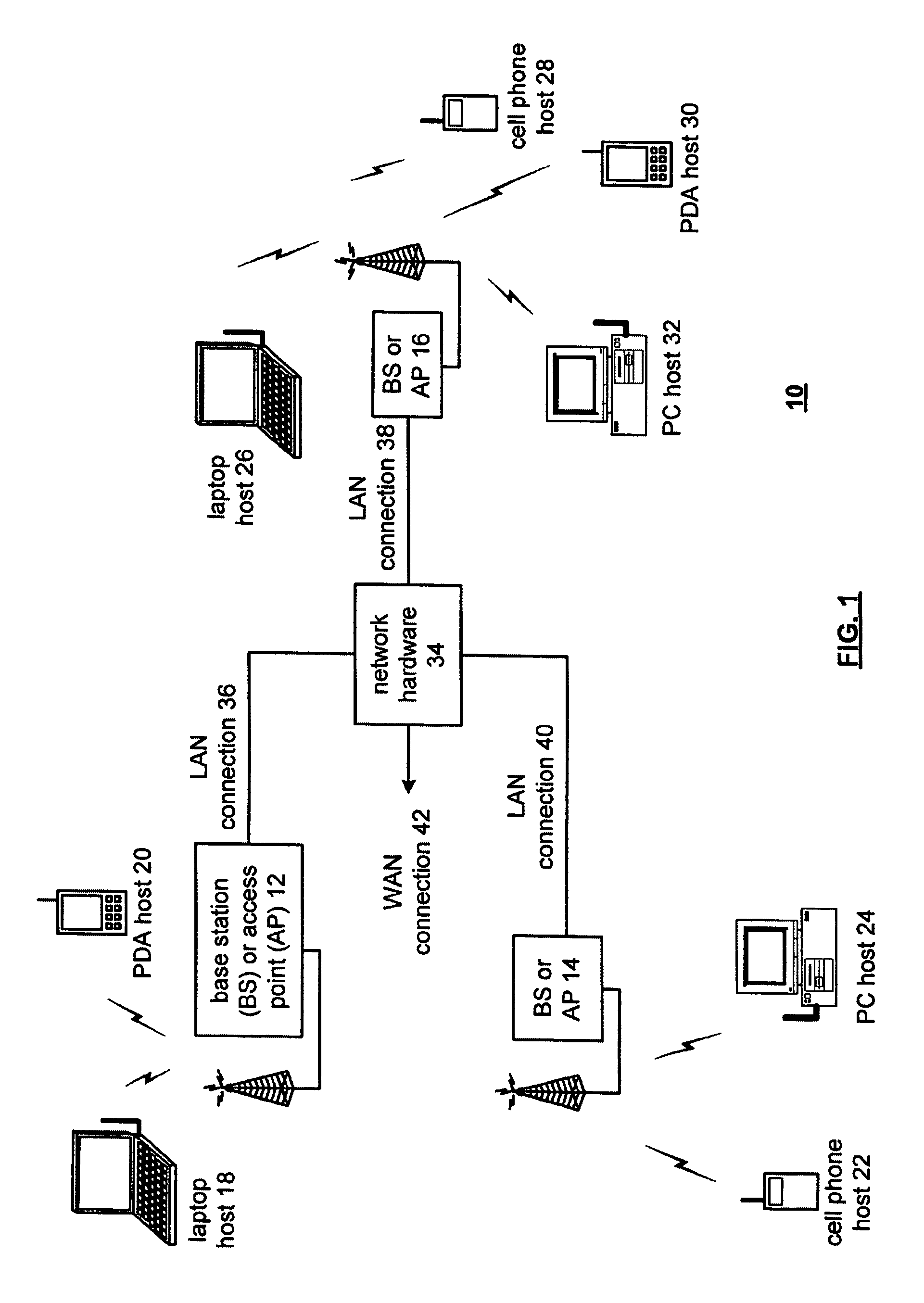
[0026]FIG. 1 is a block diagram illustrating a network system 10 according to an embodiment of the present invention. The system 10 includes a plurality of base stations and / or access points 12–16, a plurality of wireless communication devices 18–32 and a network hardware component 34. The wireless communication devices 18–32 may be lapto...


PUM


Abstract

The invention enables an increase in linearity of a power amplifier while reducing current consumption by supplying a bias current to the power amplifier in a Class AB mode.

Description

CROSS REFERENCE TO RELATED APPLICATION[0001]This application claims priority to and incorporates by reference U.S. patent application Ser. No. 60 / 606,928, filed Sep. 3, 2004, entitled “DIFFERENTIAL POWER AMPLIFIER DESIGN IN CLASS AB MODE ACHIEVING IMPROVED LINEARITY” by inventor Meng-An Pan.BACKGROUND[0002]1. Technical Field[0003]This invention relates generally to wireless communication systems, and more particularly, but not exclusively, to a non-match differential power amplifier driver (PAD) design achieving linearity of 15 dBm output 1 dB compression point with less current than the class A design case.[0004]2. Description of the Related Art:[0005]Communication systems are known to support wireless and wirelined communications between wireless and / or wirelined communication devices. Such communication systems range from national and / or international cellular telephone systems to the Internet to point-to-point in-home wireless networks. Each type of communication system is const...

Claims


Application Information

Patent Timeline
Patent Type & Authority Patents(United States)
IPC IPC(8): H03F3/45
CPCH03F3/189H03F3/45179
Inventor PAN, MENG-AN
Owner AVAGO TECH INT SALES PTE LTD
Why Eureka
Try Eureka