Method of calculating predictive shape of wire structure, calculation apparatus, and computer-readable recording medium

Active Publication Date: 2006-01-26
YAZAKI CORP
View PDF4 Cites 12 Cited by
  • Summary
  • Abstract
  • Description
  • Claims
  • Application Information

AI Technical Summary

Benefits of technology

[0012] Consequently, in view of these current situations, an object of the invention is to provide a method of calculating a predictive shape of a wiring structure for supporting a wiring design, a calculation apparatus, and a computer-readable recordin

Problems solved by technology

However, there are many kinds and forms of wiring structures such as wiring harnesses, and therefore, it has been very difficult to design a layout of wiring harnesses while accurately estimating parameters

Method used


Image

  • Method of calculating predictive shape of wire structure, calculation apparatus, and computer-readable recording medium
  • Method of calculating predictive shape of wire structure, calculation apparatus, and computer-readable recording medium
  • Method of calculating predictive shape of wire structure, calculation apparatus, and computer-readable recording medium

Examples


Embodiment Construction

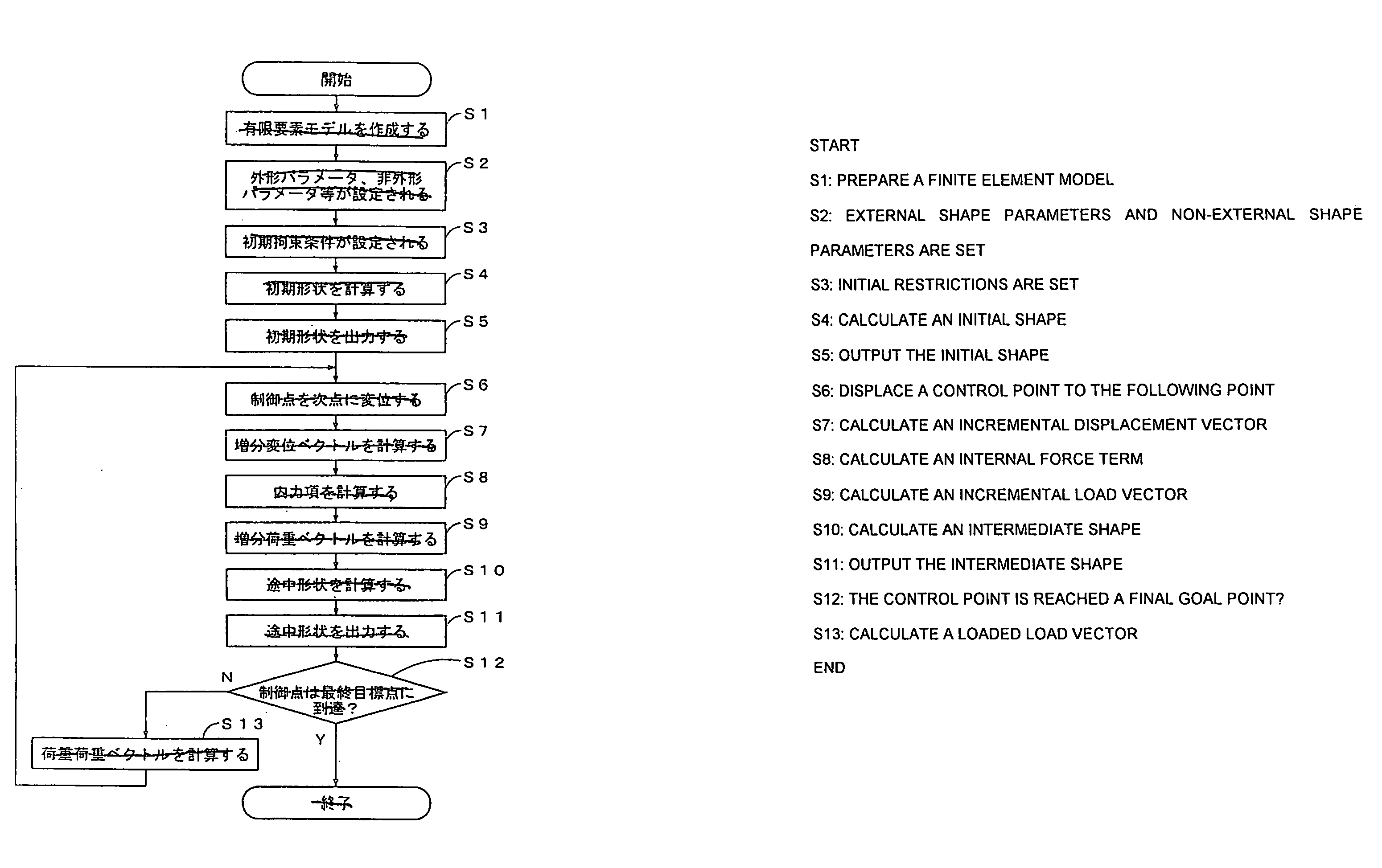
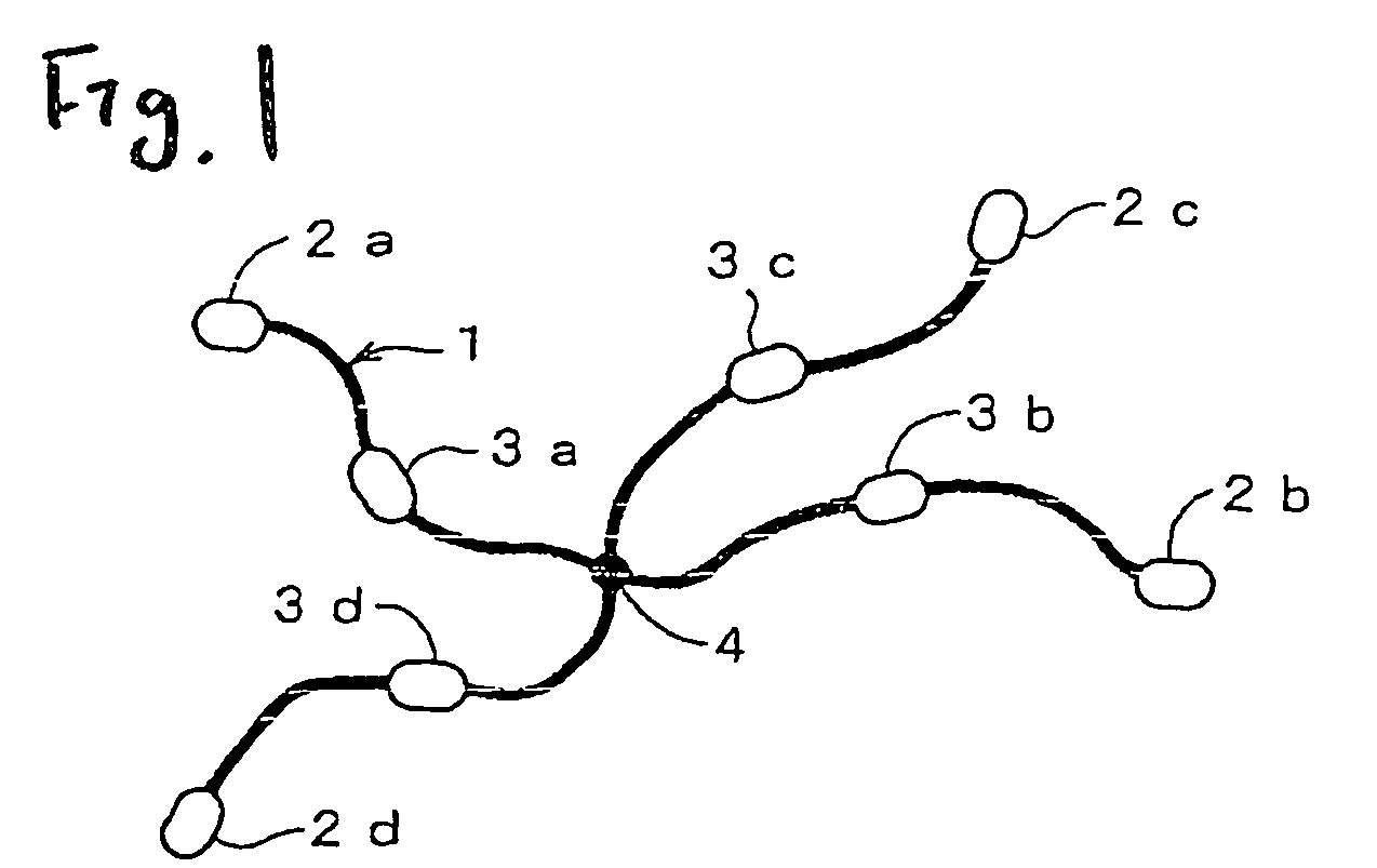
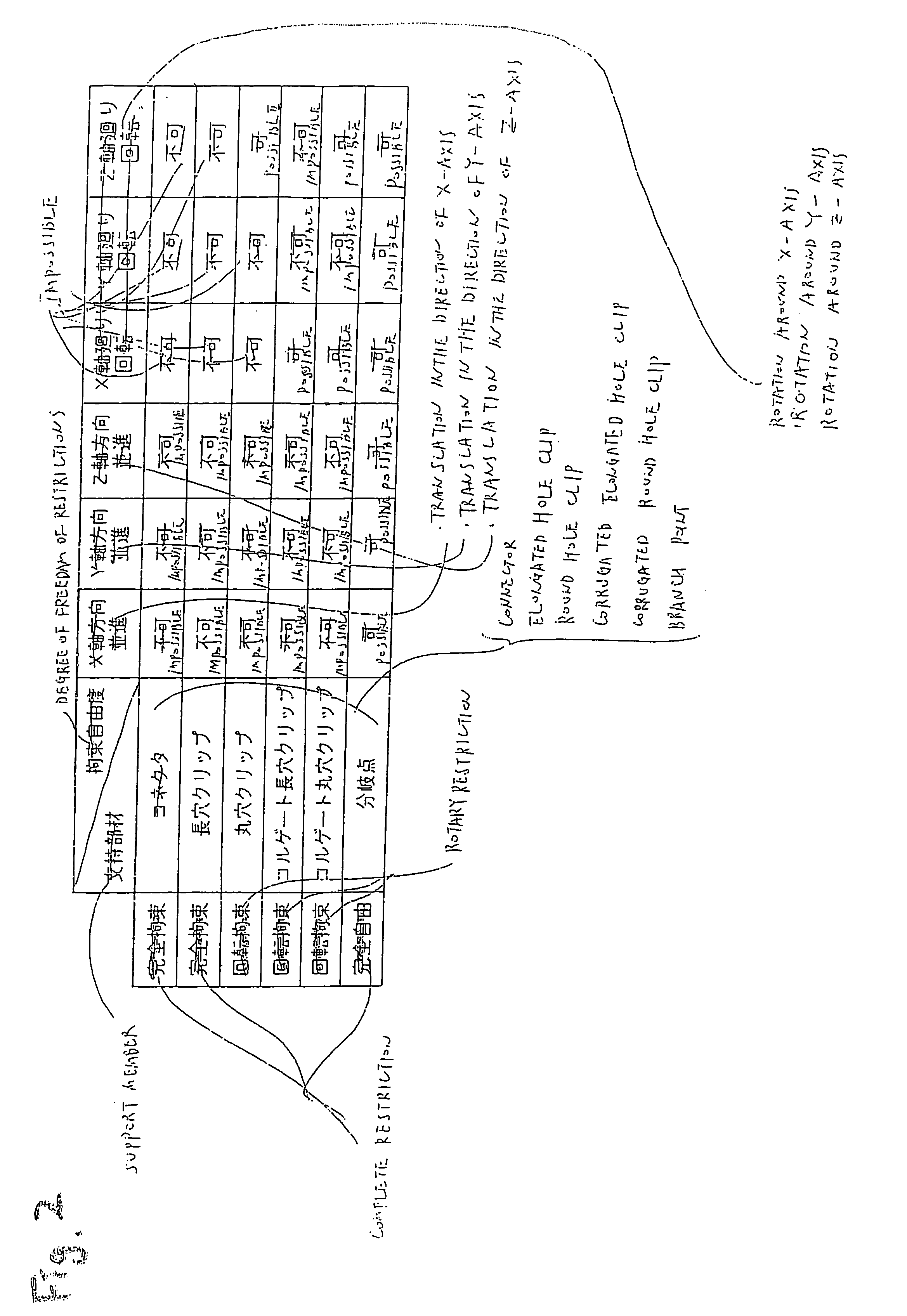
[0045] The embodiments of the present invention will now be described on the basis of the drawings. First, an example of a wire harness as an object linear structure and a typical support member will be described in FIG. 1 and FIG. 2. FIG. 1 is a drawing schematically showing an example of an object wire harness. FIG. 2 is a diagram showing the relation between typical support members fixed to the wire harness and the degree of freedom of restrictions.

[0046] Connectors 2a, 2b, 2c, 2d for connecting electric parts (not shown) are mounted at both end portions of the wire harness 1. Various kinds of clips 3a, 3b, 3b, 3c are mounted to intermediate portions of the wire harness 1, which further has a branch point 4. Since the branch lines of the wire harness 1 have basically different number and kind of structural filament members, the thickness, length, elasticity, density and the like thereof are also different.

[0047] The connectors 2a, 2b, 2c, 2d are detachably joined to fixed porti...


PUM


Abstract

A calculating apparatus includes a finite element model creating unit that creates a finite element model of the wire structure, a setting unit that sets physical properties, restriction conditions and loads of the wire structure to the finite element model, a predictive shape calculating unit that calculates a predictive shape of the finite element model in a physically balanced condition, an outputting unit that outputs the predictive shape of the finite element model, a load calculating unit that calculates the loads which are applied to the respective joints of the finite element model, a displacing unit that displaces a predetermined control point on the finite element model. The predictive shape calculating unit calculates the predictive shape of the finite element model in which the control point is displaced, based on the loads applied to the finite element model prior to the displacement of the control point.

Description

BACKGROUND OF THE INVENTION [0001] The present invention relates to a method of calculating a predictive shape of a wire structure for supporting a wiring design of the wiring structure, a calculation apparatus, and a computer-readable recording medium storing program for supporting the wiring design of the wiring structure such as a wiring harness. [0002] In vehicles or the like, a plurality of electric parts and systems are installed, and these electric parts and systems are connected by so-called wiring harnesses which are wiring structures in which filament materials such as electric wires and communication lines are bundled up by bundling members such as an insulation lock or sheathing members such as tapes. As shown in FIG. 1, a wiring harness 1 has connectors 2a, 2b, 2c, 2d, which are adapted to be connected to electric parts and systems, mounted on respective end portions thereof. In addition, various types of clips 3a, 3b, 3c, 3d are mounted at intermediate portions of the ...

Claims


Application Information

Patent Timeline
IPC IPC(8): G06F17/10
CPCB60R16/0215
Inventor SAWAI, MASAYOSHIINOUE, YOSHIHIRO
Owner YAZAKI CORP
Why Eureka
Try Eureka