Oscillator circuit, oscillator, electronic apparatus, and moving object

a technology of oscillator and oscillator, which is applied in the direction of oscillator, electrical apparatus, etc., can solve the problems of difficult to say that the relationship between control voltage and oscillation frequency is good, and the steep concentration gradient of the pn junction cannot be realized, so as to suppress the increase in circuit size and increase the frequency variation width

Inactive Publication Date: 2015-05-28
SEIKO EPSON CORP
View PDF6 Cites 11 Cited by
  • Summary
  • Abstract
  • Description
  • Claims
  • Application Information

AI Technical Summary

Benefits of technology

[0024]The oscillator, the electronic apparatus, and the moving object according to the application examples include the oscillator circuit described above including the MOS type variable capacitance elements having respective threshold voltages different from each other, and each having one end to which a control voltage is applied and the other end to which a ref

Problems solved by technology

This results from the fact that a PN junction with a steep concentration gradient cannot be realized in the process for forming the integrated circuit.
The

Method used


Image

  • Oscillator circuit, oscillator, electronic apparatus, and moving object
  • Oscillator circuit, oscillator, electronic apparatus, and moving object
  • Oscillator circuit, oscillator, electronic apparatus, and moving object

Examples


Embodiment Construction

[0035]Hereinafter, a preferred embodiment of the invention will be described in detail with reference to the accompanying drawings. It should be noted that the embodiment described below does not unreasonably limit the contents of the invention as set forth in the appended claims. Further, all of the constituents described below are not necessarily essential elements of the invention.

1. Oscillator Circuit, Oscillator

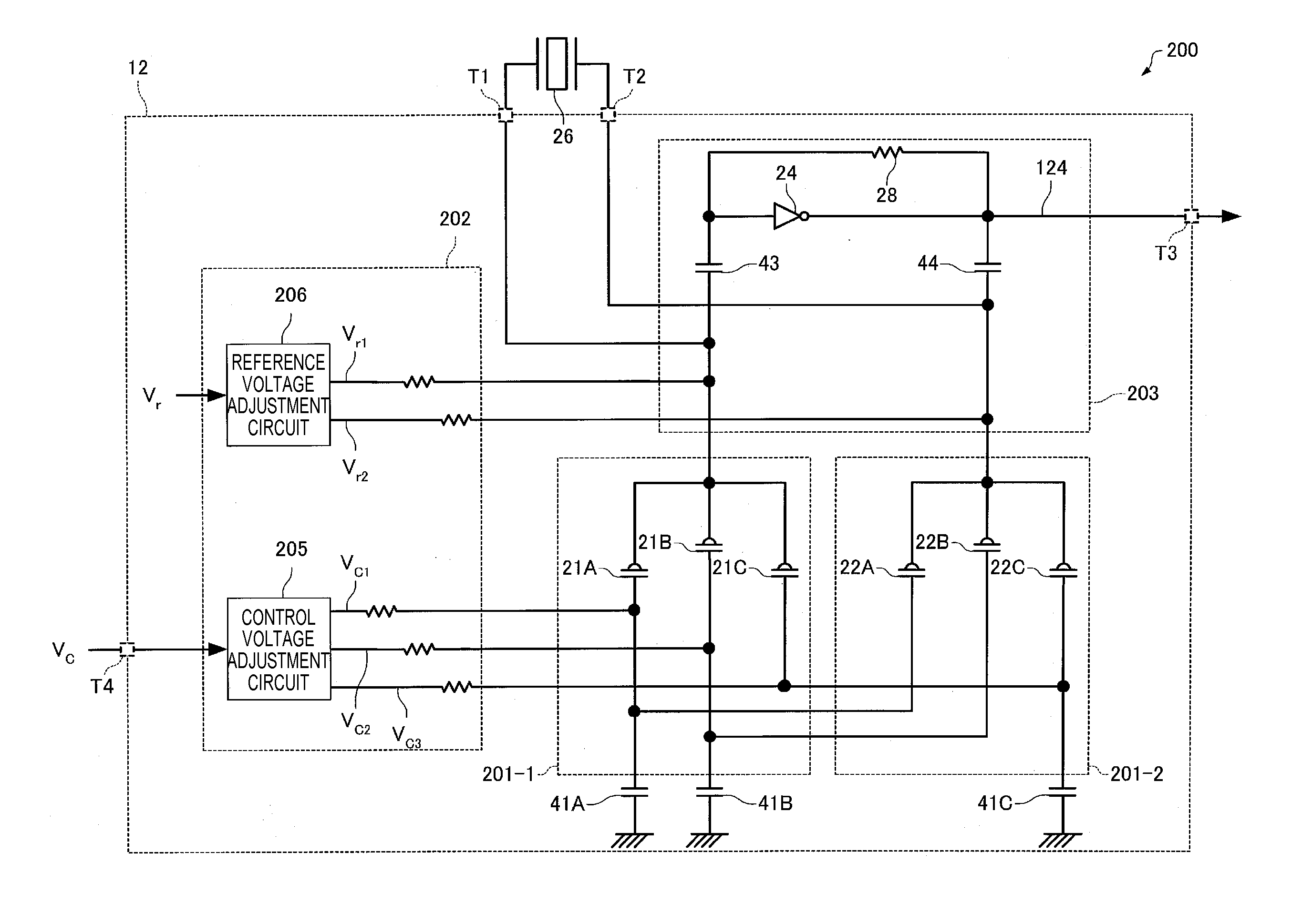
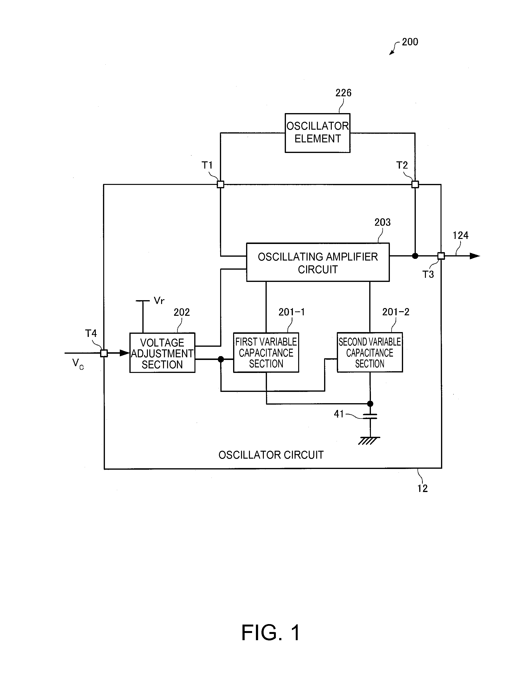
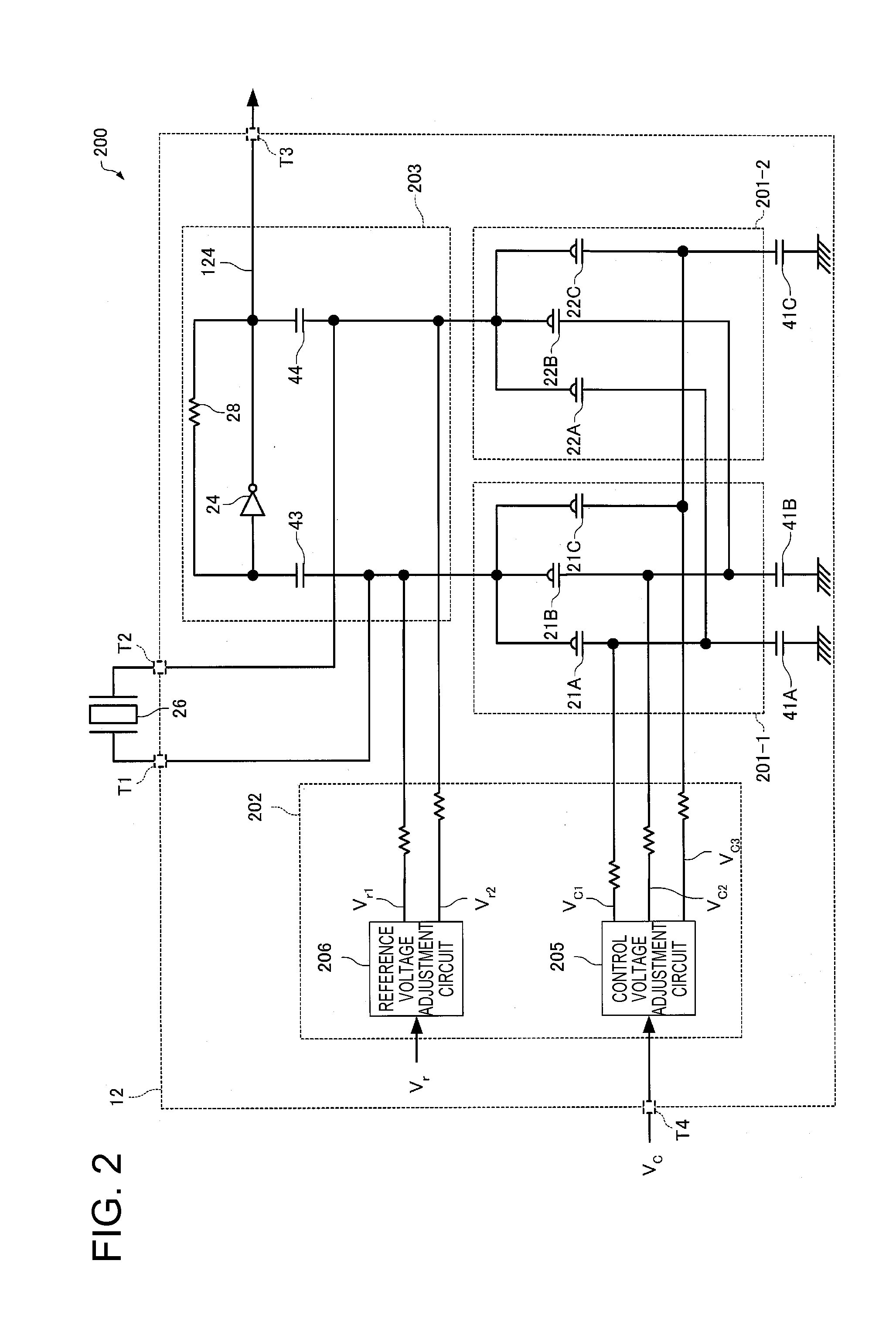
[0036]FIG. 1 is a block diagram of a vibratory device 200 including an oscillator circuit 12 according to the present embodiment. The oscillator circuit 12 includes an oscillating amplifier circuit 203 for oscillating an oscillator element 226 to generate an oscillation signal 124, a first variable capacitance section 201-1 and a second variable capacitance section 201-2 to be connected to the oscillating amplifier circuit 203, and a voltage adjustment section 202 for receiving a control voltage VC and a reference voltage Vr to perform a necessary adjustment, and supplyi...


PUM


Abstract

An oscillator circuit includes an oscillating amplifier circuit to which an oscillator element is connected, and which generates an oscillation signal, and a plurality of MOS type variable capacitance elements each having two terminals, one of which is electrically connected to the oscillating amplifier circuit, the MOS type variable capacitance elements have respective threshold voltages different from each other, a control voltage is applied to one of the terminals of each of the MOS type variable capacitance elements, and a reference voltage is applied to the other of the terminals of each of the MOS type variable capacitance elements. It is also possible for the MOS type variable capacitance elements to be different from each other in dope amount of impurities to a semiconductor layer below a gate electrode.

Description

BACKGROUND[0001]1. Technical Field[0002]The present invention relates to an oscillator circuit, an oscillator, an electronic apparatus, and a moving object.[0003]2. Related Art[0004]There has been known a method of applying a voltage to a variable capacitance element disposed inside an oscillator circuit to thereby vary the capacitance in order to make the oscillation frequency variable. The oscillator having the frequency controlled by a voltage is generally called a voltage controlled crystal oscillator (VCXO). In recent years, miniaturization is also required for crystal oscillators, and it has been progressing to making the oscillator circuit as an integrated circuit.[0005]As the variable capacitance element used in the semiconductor integrated circuit, there has been known two types, namely a varactor diode and a MOS type variable capacitance element. The varactor diode has a variation ratio (a ratio between the minimum capacitance value and the maximum capacitance value) of th...

Claims


Application Information

Patent Timeline
IPC IPC(8): H03B5/36
CPCH03B5/366H03B2201/0208H03B2200/004H03B2200/0062
Inventor ITO, HISAHIROFURUYA, YASUNARIMAKIUCHI, YOSHIKIKOBAYASHI, HITOSHI
Owner SEIKO EPSON CORP
Why Eureka
Try Eureka