Tape cartridge

a technology tape edge, which is applied in the field of tape winding layer, can solve the problems of tape edge damage, tape edge shift toward the shaft center of the hub, tape edge damage, etc., and achieve the effect of avoiding more damage to the tape edge, reducing the damage of the tape edge, and improving winding appearan

Inactive Publication Date: 2008-05-29
HITACHT MAXELL LTD
View PDF11 Cites 0 Cited by
  • Summary
  • Abstract
  • Description
  • Claims
  • Application Information

AI Technical Summary

Benefits of technology

[0013]In the present invention, the regulating body is formed so as to bulge on the rear side or the inner surface of the upper casing, and therefore when the tape cartridge receives dropping impact in the state of its upper and lower sides being reversed, the front and rear faces of the tape winding layer are supported by the hub locking structure and the regulating body. This makes it possible to prevent the tape winding layer from inclining downward to the rear section of the casing. Therefore, according to the tape cartridge of the present invention, when the tape cartridge receives large external force such as dropping impact, if becomes possible to completely remove the external force locally acting on the posterior portion of the tape winding layer so as to eliminate the damage of the tape edge, as well as to prevent the tape winding layer from gaining poor winding appearance due to such causes as a part of the outer side of the tape winding layer shifting toward the axial center of the hub. This makes it possible to obtain a tape cartridge capable of constantly maintaining the magnetic tape in an appropriate state.
[0014]If the regulating body is formed in the shape of an oblong rib and the bulge size thereof is set almost identical to the thickness size of the hub locking structure, the regulating body extending across the posterior portion of the tape winding layer can support the tape winding layer in a wide range so that large external force such as dropping impact can be received in a distributed state. Further, the front and rear faces of the tape winding layer can be supported almost simultaneously by the hub locking structure and the regulating body, so that tilting of the tape winding layer can be regulated at an early stage, and damage of the tape edge can be prevented more effectively as a whole. Moreover, the flank is formed in the side edge corner of the regulating body, and therefore when the tape winding layer tends to tilt obliquely backward, the side edge corner of the regulating body collides with the tape winding layer, which makes it possible to eliminate the external force acting locally on the tape winding layer.
[0015]According to the flank formed by rounding the bulge end face toward the inner surface side of the upper casing, the bulge end face and the flank of the regulating body are made to continue smoothly without a boundary therebetween, which makes it possible to prevent a corner section (corner) having a possibility of colliding with the tape winding layer from being formed in both ends of the regulating body, and thereby allows constant and certain elimination of damage of the tape edge.
[0016]According to the flank which is inclined downward floors the bulge and face to the inner surface side of the upper casing, a variation width of the bulge size near the boundary between the flank and the bulge end face can be increased, so that when the tape winding layer tilts within the limits of the margin size, it becomes possible to sufficiently prevent the tape winding layer from coming into contact with the flank.
[0017]If the front and rear edges of the respective bulge end face and the downward inclined face are rounded, it becomes possible to prevent the tape edge in the periphery of the tape winding layer from being damaged by coming into contact with the front and rear edges of the bulge end face and the downward inclined face, so that the damage of the tape edge can be prevented still more effectively.
[0018]If the regulating body is formed integrally with a window plate placed on the inner surface of the upper casing, the projection site of the regulating body can be decreased by the thickness size of the window plate compared with, for example, the case where the negotiating body is formed integrally with the upper casing, so that poor molding of the upper casing relating to addition of the regulating body is avoidable.

Problems solved by technology

Therefore, when the tape cartridge receives dropping impact, there is a possibility that the tape winding layer may collide with the inside wail of the main casing and the tape edge may be damaged.
Consequently, in the case where the tape cartridge receives dropping impact in the state of its upper and lower sides being reversed, the area near the rim of the posterior portion of the tape winding layer may collide with the case wall, which may cause the tape edge to be damaged or cause a part of the outside of the tape winding layer to shift toward the shaft center of the hub.

Method used


Image

  • Tape cartridge
  • Tape cartridge
  • Tape cartridge

Examples


Embodiment Construction

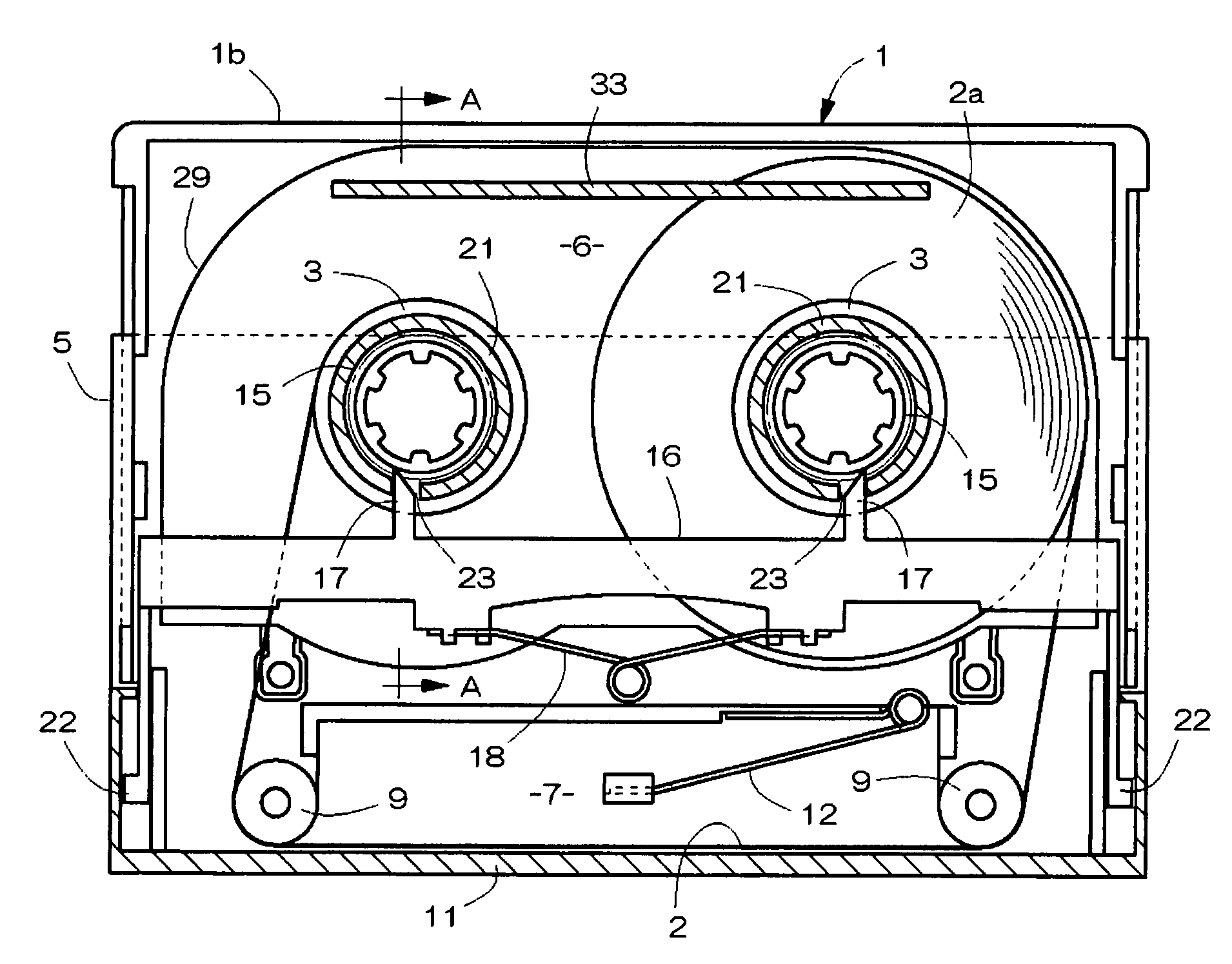
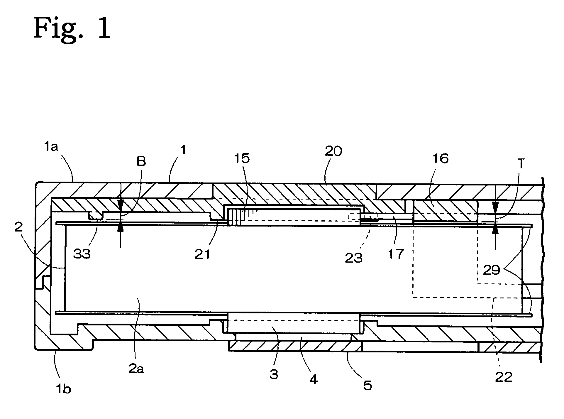
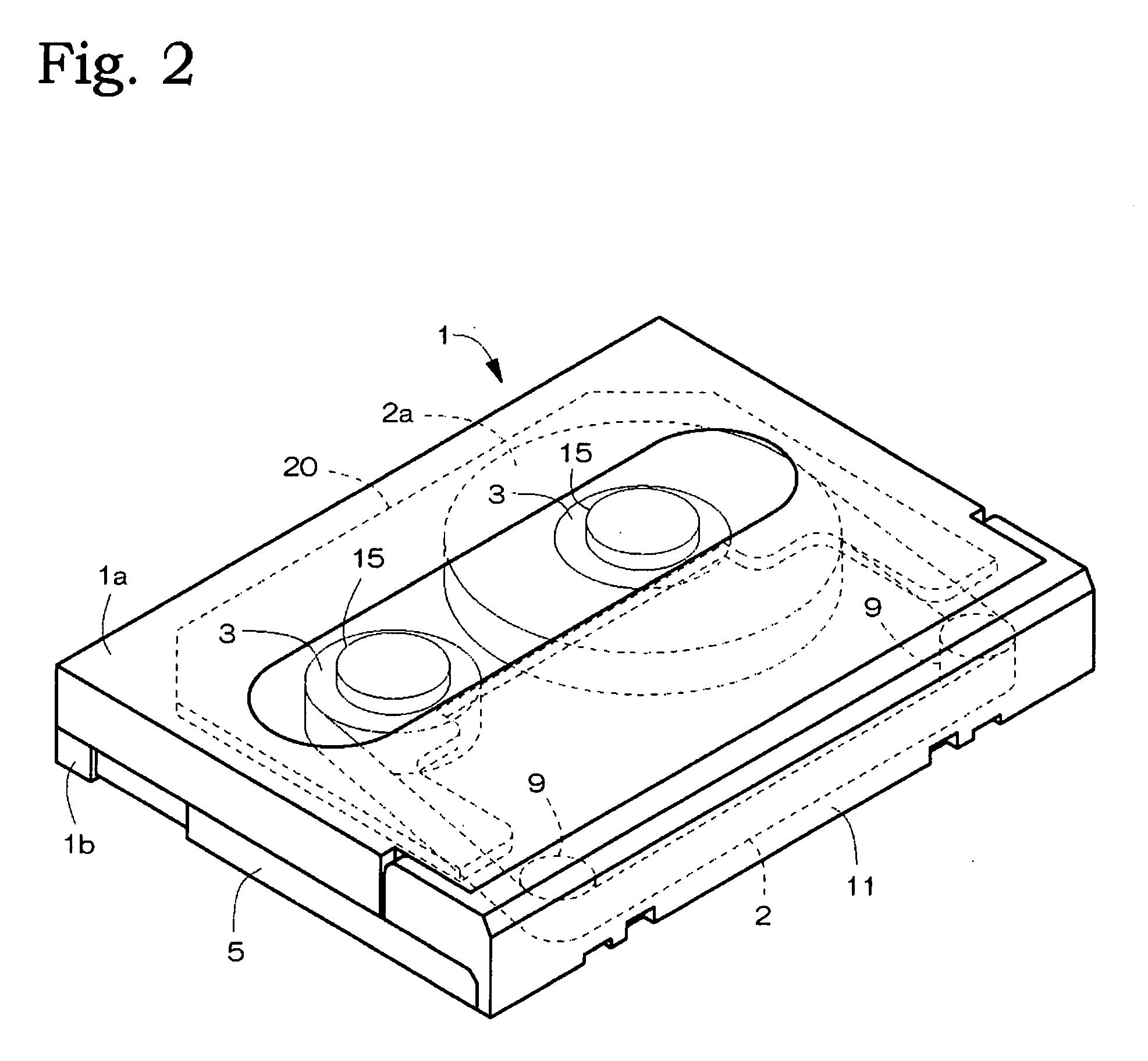
[0027]A tape cartridge in an embodiment of the present invention is shown in FIG. 1 trough FIG. 6. In FIGS. 2 and 3, the tape cartridge is structured so that a pair of right and left hubs 3, 3 for taking up a magnetic tape 2 and a hub locking structure for unrotatably locking and retaining both the hubs 3 during unused time are placed inside a thin box-like main casing 1 and that a shutter 5 which opens and closes a drive hole 4 for the hub 3 (see FIG. 1) is placed on the undersurface side of the main casing 1.

[0028]The main casing 1 is structured by joining upper and lower casings 1a, 1b which were divided into upper and lower parts, and the inside of the main casing 1 is divided into a main chamber 6 for housing the hub 3, the hub locking structure and the like, and a loading pocket 7 provided in the front part of the main chamber 6. The main chamber 6 and the loading pocket 7 are partitioned by a partition wall 8 provided in the inner surface of the upper and lower casings 1a, 1b...


PUM

PropertyMeasurementUnit
magneticaaaaaaaaaa
timeaaaaaaaaaa
thicknessaaaaaaaaaa

Abstract

To provide a tape cartridge capable of preventing an area near the posterior rim a tape winding layer from colliding with a casing wall to cause the tape edge to be damaged upon reception of dropping impact in the state where the upper and lower sides of the tape cartridge are reversed, so that the magnetic tape can constantly be maintained in an appropriate state. A pair of right and left hubs for taking up the magnetic tape, a hub locking structure are provided inside a main casing. The hub locking structure is placed on the anterior side of the inner surface of an upper casing in the main casing. A regulating body for regulating inclination of the tape winding layer is formed so as to bulge on the rear side of the inner surface of the upper casing. The regulating body is formed in an oblong rib shape having a bulge size almost identical to a thickness size of the hub locking structure in the inner surface of the upper casing. A flank for avoiding collision with the tape winding layer is formed in a side edge corner of the regulating body. The flank is formed by rounding the end section of the regulating body.

Description

BACKGROUND OF THE INVENTION[0001]The present invention relates to a tape cartridge for recording computer data and the like, and more particularly relates to a tape cartridge in which a magnetic tape is wound onto a hub.[0002]The basic structure of the tape cartridge in which the magnetic tape is wound onto the hub is publicly known, for example, in JP 6-97549 B (see 20th line in left column on third page, FIG. 3). Therein, the tape feed structure is disclosed in which hubs are placed on the right and left sides in a main casing, and a magnetic tape unreeled from one hub is reeled onto the other hub. A hub locking structure is provided inside the main casing for regulating rotation of the hub during unused time to prevent tape slacks.[0003]The hub locking structure is composed of a lock gear having lock teeth in a gear teeth shape formed on the peripheral surface, a lock frame sliding and shifting back and forth, a lock claw integrally formed with the lock frame for engaging with an...

Claims


Application Information

Patent Timeline
Patent Type & Authority Applications(United States)
IPC IPC(8): G11B23/087
CPCG11B23/08721G11B23/08785G11B23/08757
Inventor BAN, KEIJINISHIWAKI, TOSHIRO
Owner HITACHT MAXELL LTD
Why Eureka
Try Eureka