Process for the continuous production of aligned carbon nanotubes

a carbon nanotube and process technology, applied in the field of continuous can solve the problems of inability to scale up for industrial application, labor-intensive batch processing methods for production of aligned carbon nanotubes, and large batch to batch variation in the quality of nanotubes produced, so as to improve the flow characteristics

Active Publication Date: 2007-01-09
UNIV OF KENTUCKY RES FOUND
View PDF1 Cites 240 Cited by
  • Summary
  • Abstract
  • Description
  • Claims
  • Application Information

AI Technical Summary

Benefits of technology

[0014]The injector of the present invention comprises a tube-within-a-tube design configured for improved flow characteristics and feed consistency of the feed solution/carrier gas stream entering the reactor. In a presently preferred embodiment, the injector comprises a first hollow tube for delivering the feed solution as described supra and a second hollow tube for delivering the inert carrier gas. The fir

Problems solved by technology

Currently utilized technologies for production of aligned carbon nanotubes are labor intensive, costly, inefficient, and are not amenable to scale-up for industrial applicability.
While effective, batch processing methods for production of carbon nanotubes, particularl

Method used


Image

  • Process for the continuous production of aligned carbon nanotubes
  • Process for the continuous production of aligned carbon nanotubes
  • Process for the continuous production of aligned carbon nanotubes

Examples


example 1

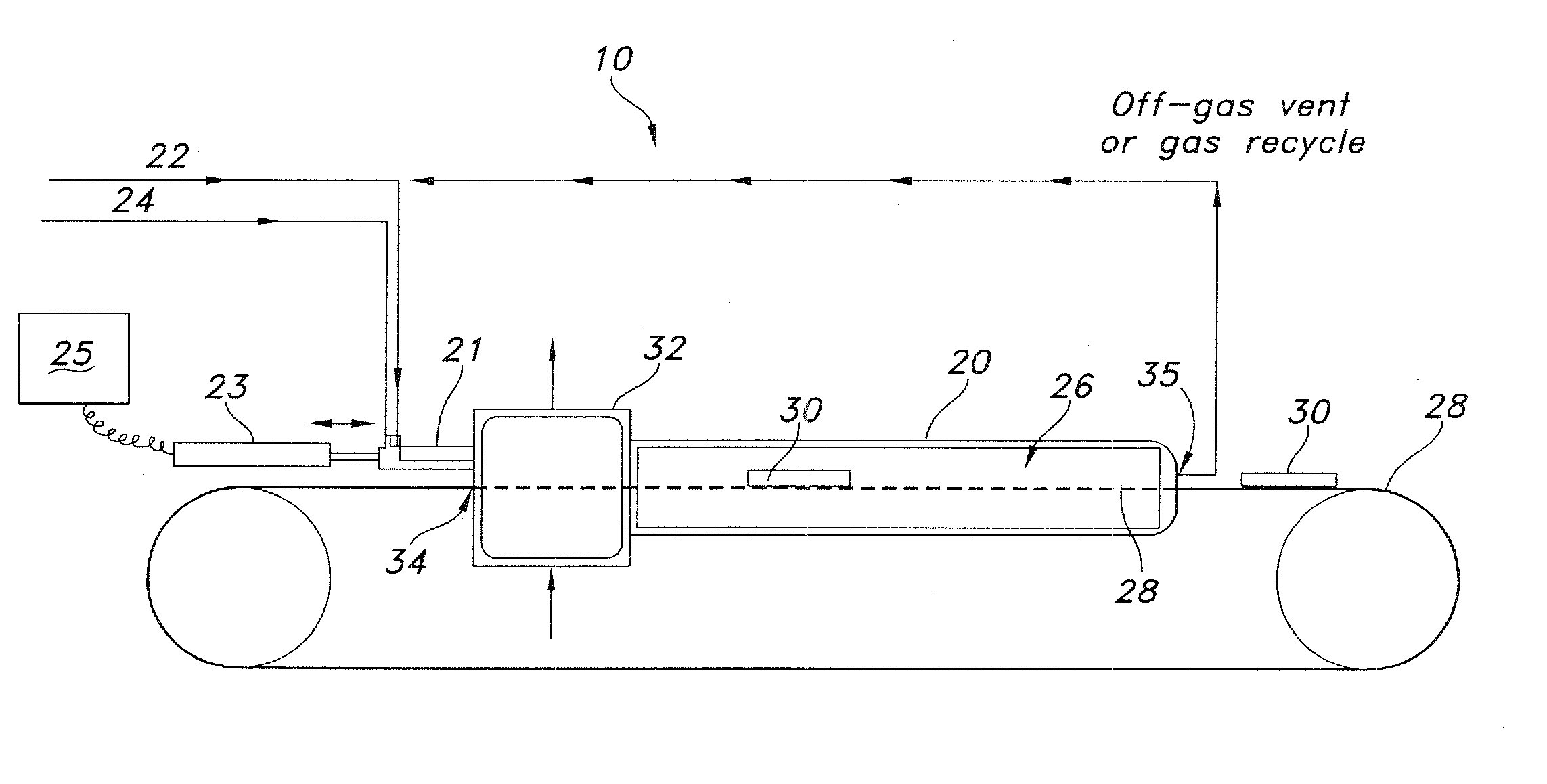
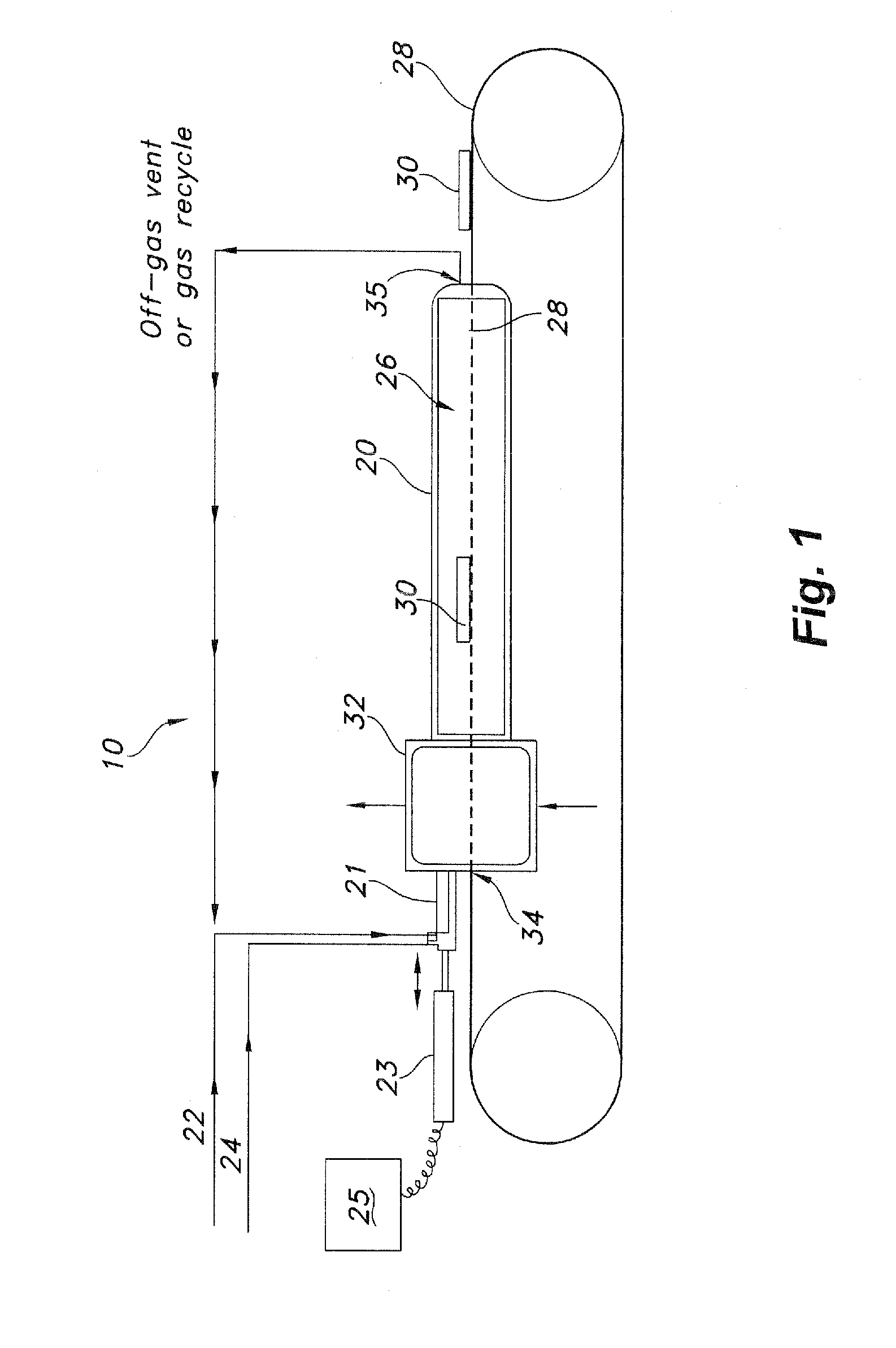
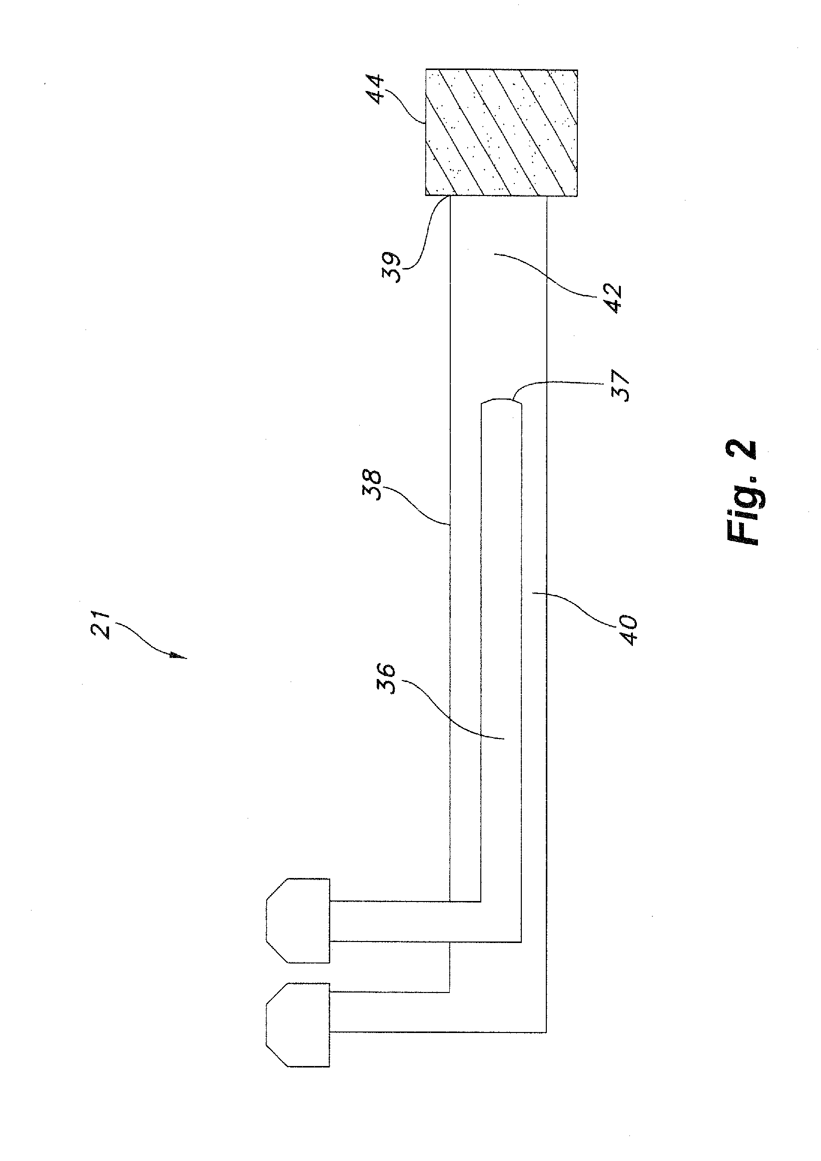
[0042]A device for continuous production of aligned carbon nanotubes was constructed in accordance with the method and apparatus as disclosed herein. A furnace of known design having the dimensions of 2 inches by 3 feet, with 3 heating zones including a 2 foot long reaction zone was utilized as the reactor. The final temperature in the reaction zone was brought to 800 C. A feed solution of ferrocene (2.3 g) and xylene (20 g) was prepared. The feed solution was injected into the reactor through an injector as described herein, having a first (feed solution delivering) tube with an outer diameter of 3.12 mm and a second (carrier gas delivering) tube with an inner diameter of 3.75 mm, and a dispersion chamber having a length of 1.5 inches.

[0043]Argon / hydrogen carrier gas flow was initiated and brought to 1200 sccm (1080 sccm Ar, 120 sccm H2). Feed solution was delivered into the reaction zone at a flow rate of 2.70 ml / h−1. A conveyor belt as shown in FIG. 1 was activated, and delivered...

example 2

[0049]The device of this invention was prepared substantially as described in Example 1, with the exception that a batch procedure for production of aligned carbon nanotubes was conducted rather than the continuous procedure of Example 1. All other conditions were maintained as in Example 1. The feed solution as disclosed in Example 1 was passed through stainless steel sinters as described herein, placed terminally on the injector adjacent the dispersion chamber. Sinters having poresizes of 0.2 μm and 0.5 μm were compared to negative controls (no sinter). Feed solution composition and run conditions were as described for Example 1, with the exception of use of a batch procedure.

[0050]As seen in FIG. 4, passing the feed solution through sinters having successively smaller pore sizes reduces both the maximum diameter and the average diameter of carbon nanotubes produced. Similarly, as sinter pore size is reduced, the overall diameter size distribution of the carbon nanotubes produced ...


PUM


Abstract

Novel methods and apparati for continuous production of aligned carbon nanotubes are disclosed. In one aspect, the method comprises dispersion of a metal catalyst in a liquid hydrocarbon to form a feed solution, and volatilizing the feed solution in a reactor through which a substrate is continuously passed to allow growth of nanotubes thereon. In another aspect, the apparatus comprises a reactor, a tube-within-a-tube injector, and a conveyor belt for passing a substrate through the reactor. The present invention further discloses a method for restricting the external diameter of carbon nanotubes produced thereby comprising passing the feed solution through injector tubing of a specified diameter, followed by passing the feed solution through an inert, porous medium. The method and apparati of this invention provide a means for producing aligned carbon nanotubes of a particular external diameter which is suitable for large scale production in an industrial setting.

Description

[0001]This application claims the benefit of U.S. Provisional Patent Application Ser. Nos. 60 / 289,415 filed May 8, 2001, 60 / 289,745 filed May 9, 2001, and 60 / 356,272 filed Feb. 11, 2002.[0002]This invention was made with Government support under NSF-MRSEC grant DMR-9809606. The Government may have certain rights in this invention.TECHNICAL FIELD[0003]The present invention relates to methods for producing aligned carbon nanotubes, and more particularly to methods and apparati for continuous production of aligned carbon nanotubes. The invention further relates to methods and apparati for continuous production of aligned carbon nanotubes which do not require patterned substrates, and which further produce quantities of high quality, homogenous populations of nanotubes.BACKGROUND OF THE INVENTION[0004]Aligned carbon nanotubes have application in numerous areas of composite materials, such as for use in separation media, as catalysts, as catalyst supports, in energy storage and transfer,...

Claims


Application Information

Patent Timeline
IPC IPC(8): D01C5/00D01F9/12
CPCB82Y30/00D01F9/127B82Y40/00C01B31/024Y10S977/742C01B32/164
Inventor JACQUES, DAVID N.ANDREWS, RODNEY J.
Owner UNIV OF KENTUCKY RES FOUND
Why Eureka
Try Eureka