Optical transceiver

a transceiver and optical technology, applied in the field of optical transceivers, can solve the problems of not being able to apply the optical transceiver having the prior, and the reception cannot be carried out normally, and achieve the effect of reducing near-end crosstalk

Inactive Publication Date: 2007-04-03
ROHM CO LTD
View PDF12 Cites 3 Cited by
  • Summary
  • Abstract
  • Description
  • Claims
  • Application Information

AI Technical Summary

Benefits of technology

[0010]In view of the problems of the prior art described above, it is an object of the present invention to provide an optical transceiver which makes it possible to adjust the emission direction of the trans...

Problems solved by technology

However, when high-level reception signal light is incident on the light receiving element during the transmission state, the reception circuit is temporarily blinded, and there is the risk that reception can not be carried...

Method used


Image

  • Optical transceiver
  • Optical transceiver
  • Optical transceiver

Examples


first embodiment

of the Invention

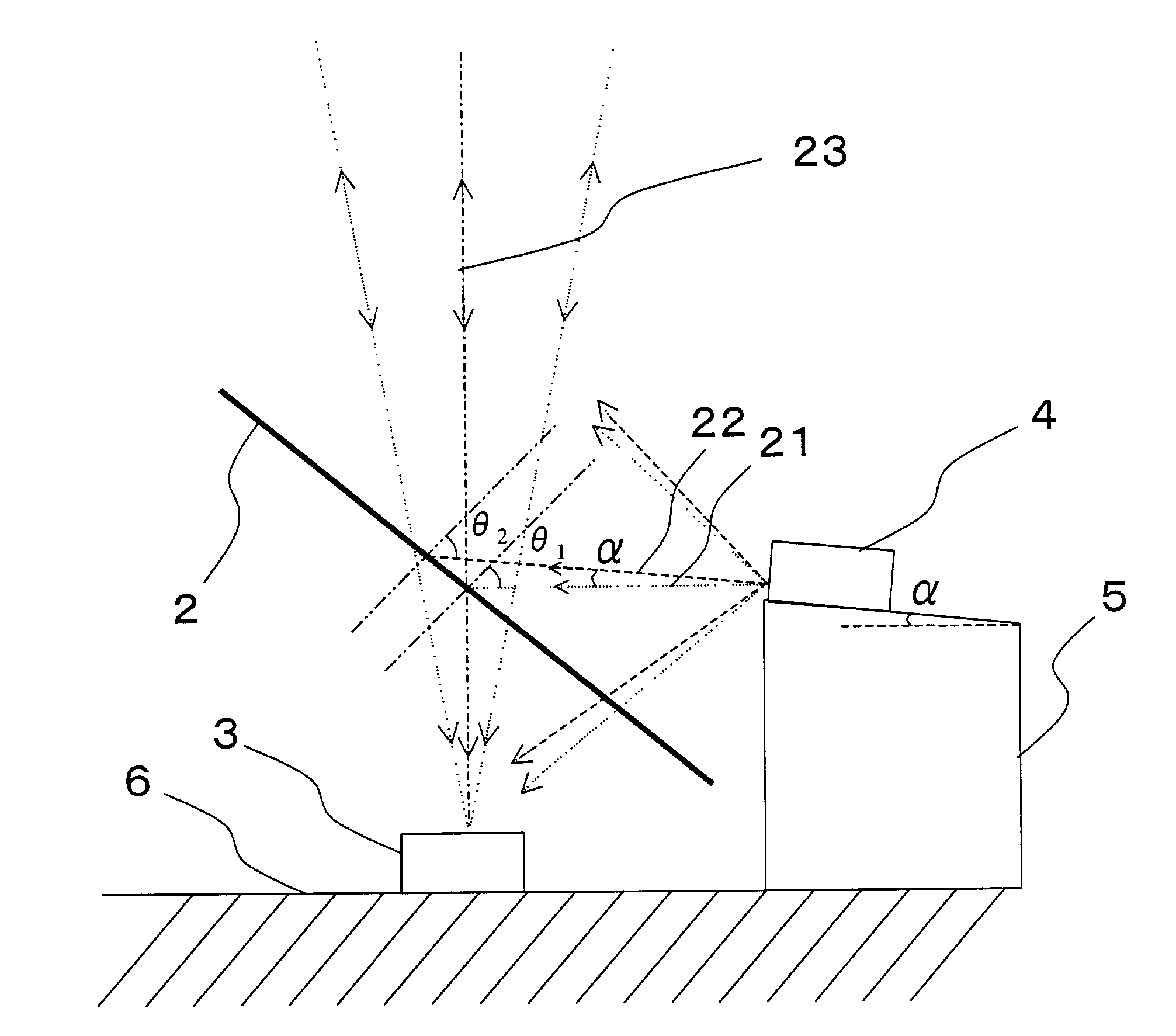
[0058]FIG. 2a and FIG. 2b show an embodiment of the present invention applied to a same wavelength, direction division multiplexing, single-fiber, bi-directional transmission system in which the optical plate is limited to a half mirror.

[0059]FIG. 2a is a rough explanatory drawing of an optical transceiver according to the present embodiment, and FIG. 2b is a rough explanatory drawing showing an enlarged view of a main portion thereof. In order to apply the optical transceiver to a same wavelength, direction division multiplexing, single-fiber, bi-directional transmission system, the present embodiment has the distinctive feature of being constructed so as to prevent near-end crosstalk caused by the transmission signal light from the light emitting element being incident on the light receiving element inside the optical transceiver. A detailed description is given below with reference to the drawings.

[0060]As shown in FIG. 2a, reception signal light from an optical t...

second embodiment

of the Invention

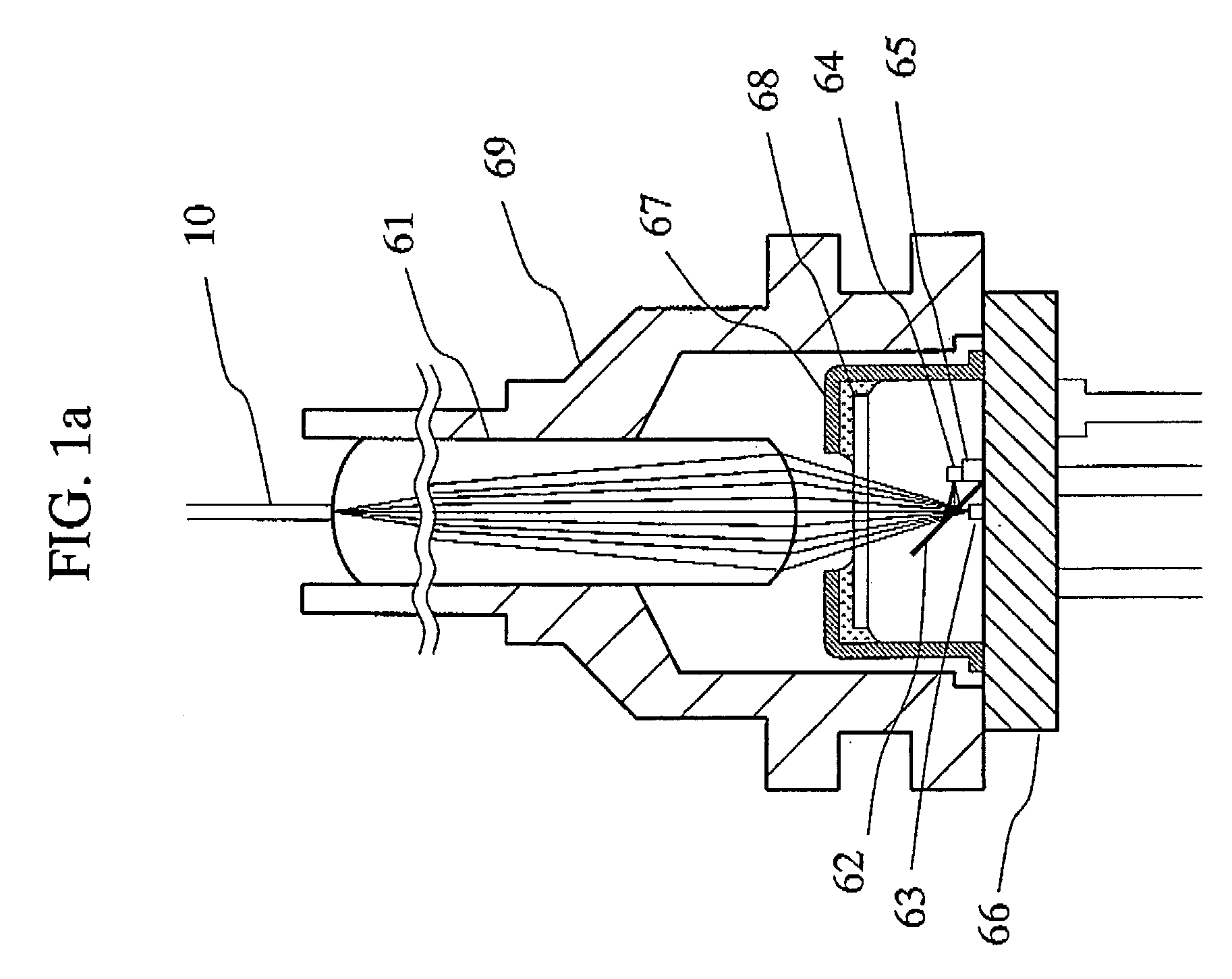
[0069]FIG. 4 shows an embodiment of the present invention applied to a same wavelength, direction division multiplexing, single-fiber, bi-directional transmission system in which the optical plate is formed by a half mirror.

[0070]FIG. 4 is a rough explanatory drawing showing an enlarged view of a main portion of the optical transceiver. In order to apply the optical transceiver to a same wavelength, direction division multiplexing, single-fiber, bi-directional transmission system, the present embodiment has the distinctive feature of being constructed so as to reduce near-end crosstalk caused by the transmission signal light from the light emitting element being incident on the light receiving element inside the optical transceiver.

[0071]A detailed description is given below with reference to the drawings. Namely, in order to make manufacturing easy, normally the laser diode is mounted to the top surface of the submount which is parallel to the top surface of the sys...

third embodiment

of the Invention

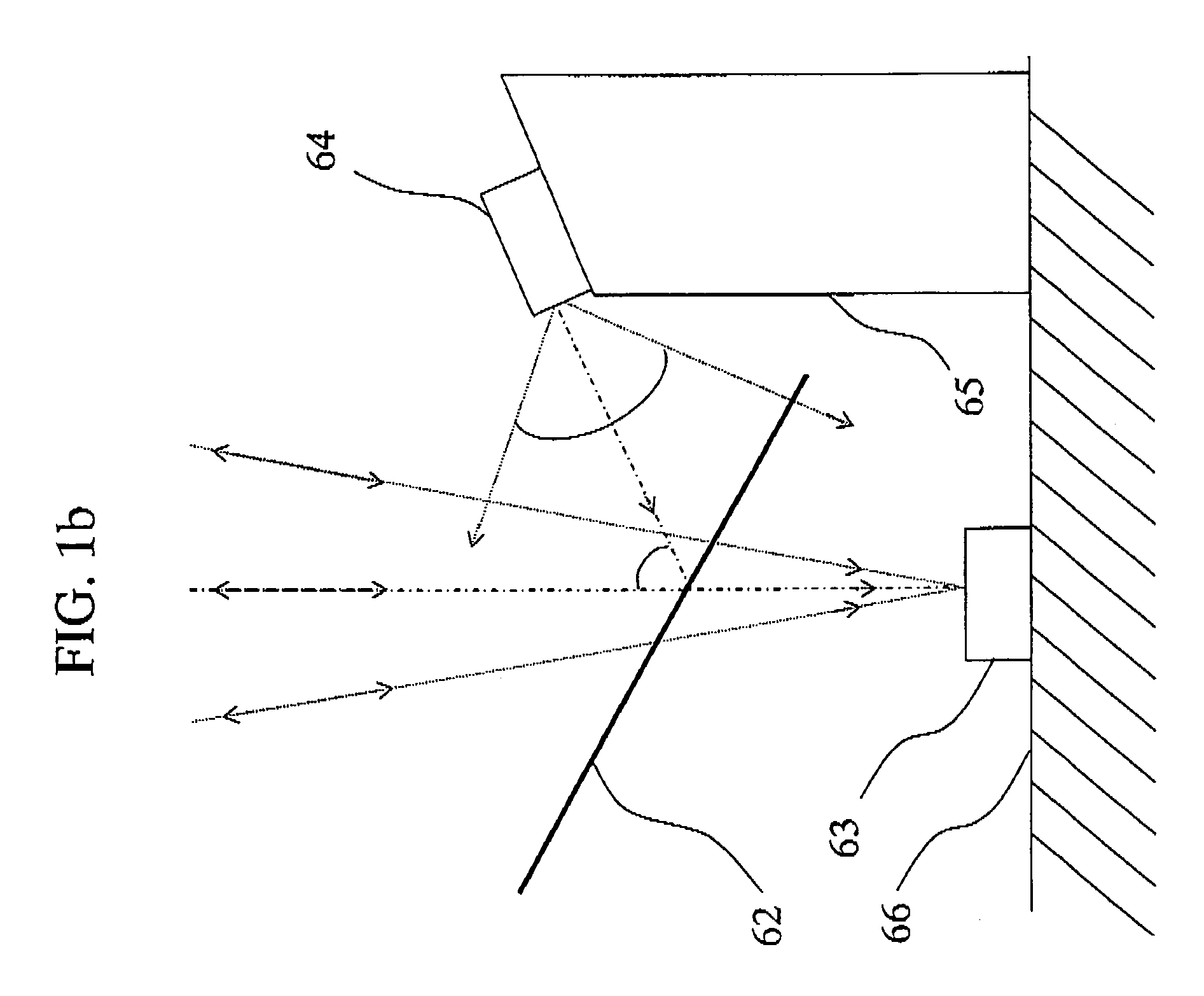
[0076]FIG. 5 shows an embodiment of the present invention applied to a same wavelength, direction division multiplexing, single-fiber, bi-directional transmission system in which the optical plate is formed by a half mirror. FIG. 5 is an enlarged view of a main portion of the optical transceiver. In this embodiment, when the beam expansion of the transmission signal light of a laser diode 14 is smaller than or equal to the original maximum beam expansion angle of the transmission signal light from the laser diode 14 condensed to the optical transmission path by the half mirror and the coupling lens, there is little degradation of the amount of the transmission signal light from the laser diode 14 condensed in the optical transmission path even when the emission direction of the transmission signal light from the laser diode 14 is moved slightly.

[0077]Namely, with the laser diode 14 mounted to a submount 15 so that the substrate plane of the laser diode 14 is perpendi...


PUM


Abstract

An optical transceiver is equipped with at least one coupling lens which condenses reception signal light from an optical medium and condenses transmission signal light to the optical medium, an optical plate which passes the reception signal light and reflects the transmission signal light, a light receiving element which receives the reception signal light passed through the optical plate, and a light emitting element which transmits the transmission signal light so as to be reflected by the optical plate, wherein an emission port of the transmission signal light of the light emitting element is arranged at a position to enable the transmission signal light from the light emitting element to form an image in the optical medium via the optical plate and the coupling lens, and wherein the emission port of the transmission signal light of the light emitting element is arranged in a direction that makes the incident angle formed on the optical plate by the beam center line of the transmission signal light transmitted from the light emitting element larger than the incident angle of the beam center line for maximally condensing the transmission signal light from the light emitting element to the optical medium in order to move the beam center line of the transmission signal light from the light emitting element away from the light receiving element, whereby it becomes possible to reduce the near-end crosstalk from the light emitting element to the light receiving element in the optical transceiver.

Description

BACKGROUND OF THE INVENTION[0001]1. Field of the Invention[0002]The present invention is related to an optical transceiver which carries out bi-directional communication simultaneously with the same or different wavelengths using one optical fiber for transmission and reception, or an optical transceiver which carries out reading and writing operations on an optical disc.[0003]2. Description of the Prior Art[0004]The prior art will be described with reference to FIG. 1a and FIG. 1b. FIG. 1a is a rough explanatory drawing of an example prior art optical transceiver, and FIG. 1b is a rough explanatory drawing of a main portion thereof. This prior art example is an optical transceiver which is used in a same wavelength, time division multiplexing, single-fiber bi-directional transmission system.[0005]Namely, the same wavelength, time division multiplexing, single-fiber, bi-directional transmission system is a system which uses the same wavelength for the upstream signals and the downst...

Claims


Application Information

Patent Timeline
IPC IPC(8): H04B10/00G02B6/42G02B6/26H01S5/022H04B10/25H04B10/2507H04B10/40H04B10/50H04B10/60H04B10/80
CPCH04B10/1143
Inventor TSUMORI, MASAHIKOTANAKA, HARUOYAMAZAKI, TOMOHIRO
Owner ROHM CO LTD
Why Eureka
Try Eureka