Fixing apparatus and image forming apparatus

a technology of fixing apparatus and fixing plate, which is applied in the direction of electrographic process apparatus, instruments, optics, etc., can solve the problems of affecting the quality of the paper, the lateral edge of the paper plate is inevitably curled, and the end parts of the press roller cannot transport paper sheets as efficiently as the middle part, so as to prevent the paper sheet from being creased and curled

Active Publication Date: 2007-04-10
KK TOSHIBA +1
View PDF8 Cites 7 Cited by
  • Summary
  • Abstract
  • Description
  • Claims
  • Application Information

AI Technical Summary

Benefits of technology

[0009]The object of an embodiment of this invention is to provide a fixing apparatus and an image forming apparatus, which can maintain the end parts and middle part of a heat roller at the same temperature, thereby to prevent paper sheets from being creased and curled.

Problems solved by technology

Once the hardness of the end parts of the press roller has more decreased than the middle part of the press roller, the end parts of the press roller cannot transport paper sheets so efficiently as the middle part.
Further, when the end parts of the press roller rise to a higher temperature than the middle part of the press roller, much water evaporates from the lateral edges of the paper sheet.
The paper sheet is inevitably curled.

Method used


Image

  • Fixing apparatus and image forming apparatus
  • Fixing apparatus and image forming apparatus
  • Fixing apparatus and image forming apparatus

Examples


Embodiment Construction

[1] An embodiment of this invention will be described, with reference to the accompanying drawings.

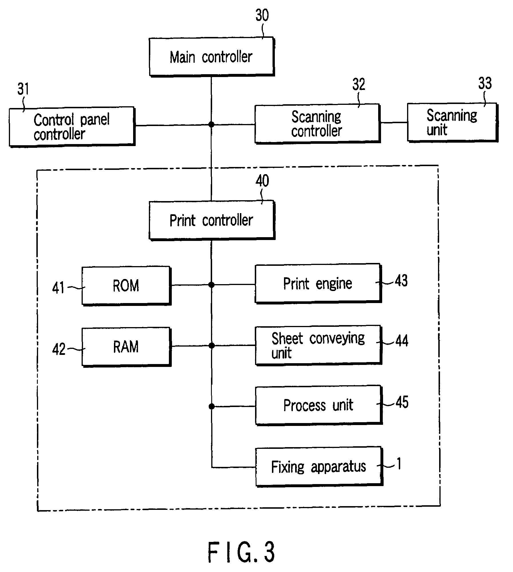
[0034]An image forming apparatus according to the invention comprises a scanning unit (i.e., scanning unit 33, described later), a process unit (i.e., process unit 45, described later), and a fixing apparatus (i.e., fixing apparatus 1, described later). The scanning unit optically reads images from documents. The process unit forms develop images corresponding to the images ready by the scanning unit, on paper sheets to which the images will be fixed. The fixing apparatus heats developer images formed on paper sheets, thus fixing them to the paper sheets. The structure of the image forming apparatus is disclosed in application Ser. No. 10 / 602,920 already filed, and will not be described.

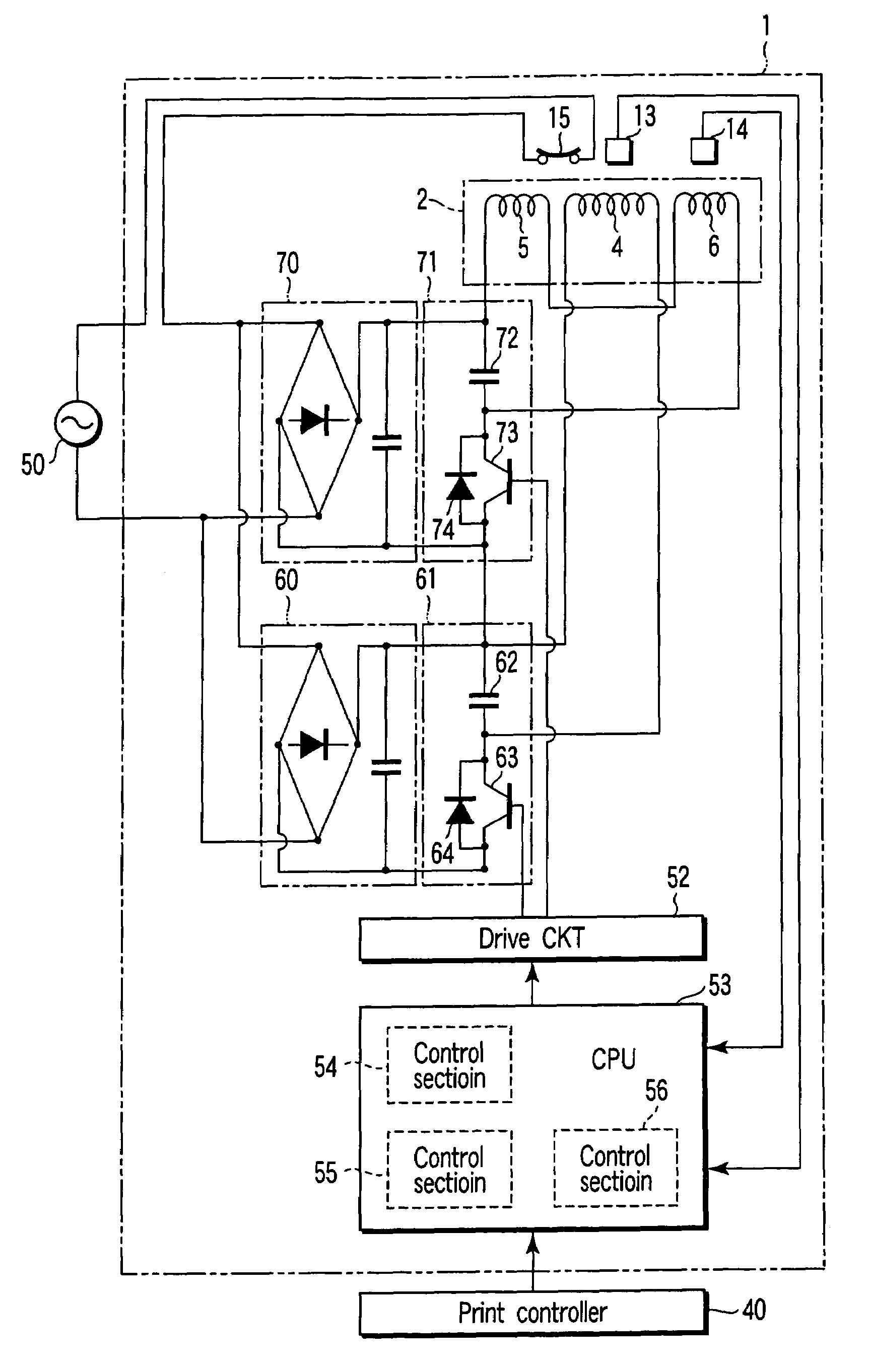
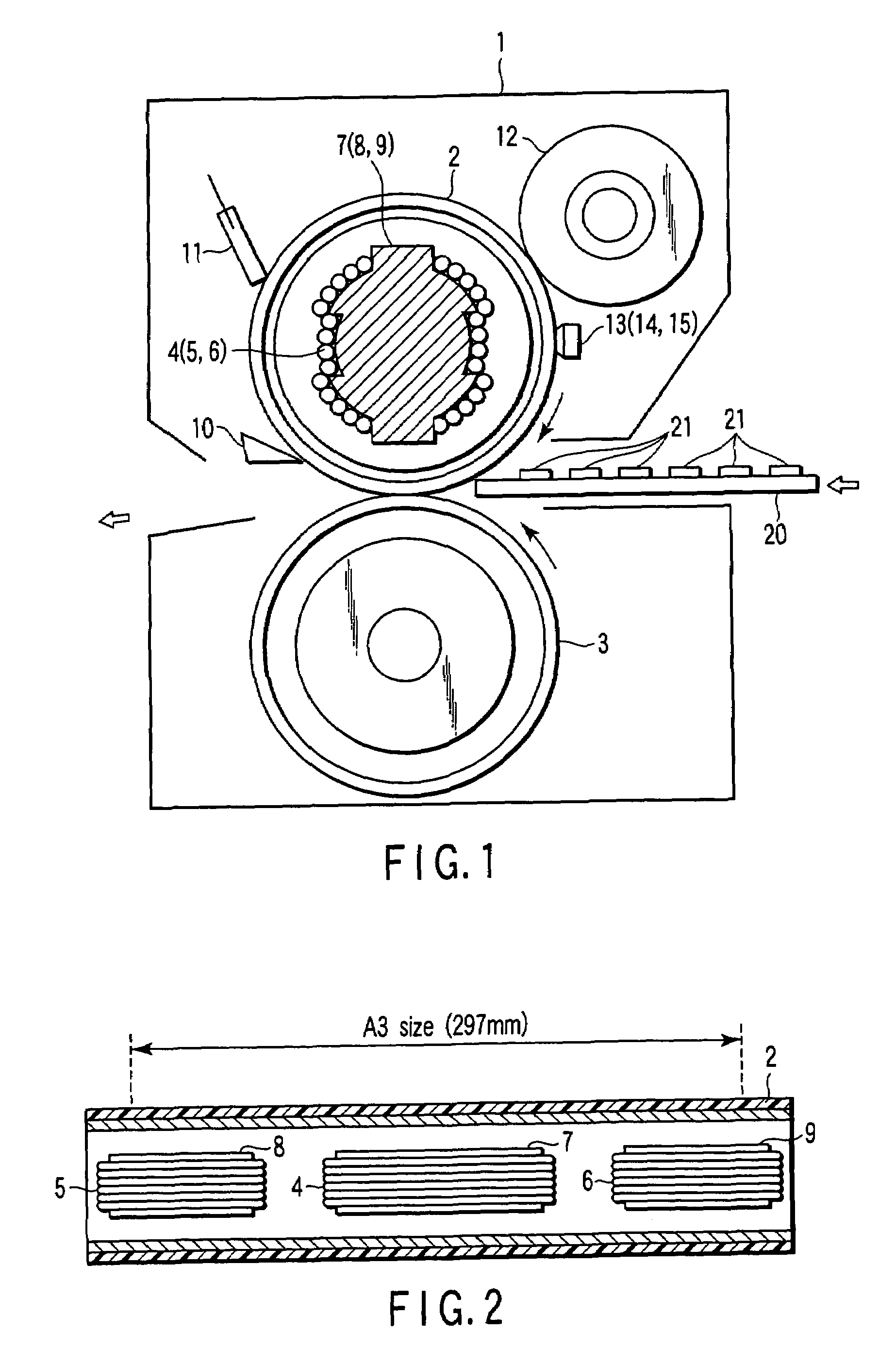
[0035]FIGS. 1 and 2 show the structure of the fixing apparatus.

[0036]The fixing apparatus 1 has a rotary heat member, e.g., a heat roller 2. The heat roller 2 is provided on a press roller 8, i.e., a pr...


PUM


Abstract

If the temperature T1 of the middle part of a heat roller 2 is higher than the temperature T2 of the end parts of the heat roller 2 [T1≧(T2−X)], the operating time B of side coils 5 and 6 is set longer than the operating time A of a center coil. If the temperature T1 of the middle part of a heat roller 2 is lower than the temperature T2 of the end parts of the heat roller 2 [T1<(T2−X)], the operating time A of the center coil is set longer than the operating time B of side coils 5 and 6.

Description

BACKGROUND OF THE INVENTION[0001]Image forming apparatuses read images from documents, form developer images corresponding to the images read, on paper sheets, and fix the developer images on the paper sheets by using a fixing apparatus.[0002]In the fixing apparatus, a paper sheet is held between the heat roller and the press roller, and heat and pressure are applied to the paper sheet. The developer image on the paper sheet is thereby fixed.[0003]A center coil and side coils are provided within or outside the heat roller. These coils generate high-frequency magnetic fields when a high-frequency current is supplied to them. From the high-frequency magnetic fields there are generated eddy currents. The eddy currents turn into Joule heat. The Joule heat heats the heat roller. A fixing apparatus of induction heating type is disclosed in, for example, Jpn. Pat. Appln. KOKAI Publication No. 2001-312178.[0004]The center coil performs induction heating at that part of the heat roller which...

Claims


Application Information

Patent Timeline
Patent Type & Authority Patents(United States)
IPC IPC(8): G03G15/20H05B1/00
CPCG03G15/2042
Inventor KIKUCHI, KAZUHIKO
Owner KK TOSHIBA
Why Eureka
Try Eureka