Aiming sight having fixed light emitting diode (LED) array and rotatable collimator

a technology of light-emitting diodes and aiming sights, which is applied in the field of aiming sights, can solve the problems of introducing significant parallax aiming errors, limited aiming of leaf sights, and relatively slow rotation of entire aiming sights, and achieves constant focal distance

US7225578B2Active Publication Date: 2007-06-05EOTECH LLC
13 Cites 56 Cited by

Patent Information

Authority / Receiving Office
US · United States
Patent Type
Patents(United States)
Current Assignee / Owner
Publication Date
2007-06-05

Smart Images

  • Figure 1
    Figure 1
  • Figure 2
    Figure 2
  • Figure 3
    Figure 3
Patent Text Reader

Abstract

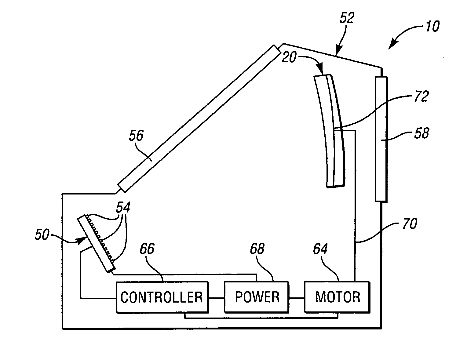
An aiming sight includes a controller, a power supply, an LED array, and a collimator. The power supply powers the LEDs to turn-on and turn-off, and powers the collimator to rotate. The collimator rotates to different rotational positions while the controller, the power supply, and the LED array remain fixed in place. The LEDs are positioned such that one LED and the collimator are at a constant angle and separated by a constant focal distance for each collimator position. The controller controls the collimator to rotate to a collimator position to generate an aiming dot at an angular position corresponding to the collimator position. The controller turns-on the LED which is at the constant angle and separated from the collimator by the constant focal distance and turns-off the remaining LEDs such that the collimator collimates light from the turned-on LED into the aiming dot at the angular position corresponding to the collimator position.
Need to check novelty before this filing date? Find Prior Art

Description

BACKGROUND OF THE INVENTION

[0001] 1. Field of the Invention

[0002] The present invention generally relates to aiming sights for use with firearms and, more particularly, to an aiming sight having a fixed light emitting diode (LED) array and a rotatable collimator which function together to change angular position of an aiming dot such that the aiming dot has parallax-free performance over a relatively large elevation angle adjustment range.

[0003] 2. Background Art

[0004] Certain firearms launch relatively low-velocity projectiles such as grenades, air burst ammunition, and non-lethal rubber bullets. Low-velocity projectile firearms require aiming sights having a wide elevation angle adjustment range because the amount of projectile drop increases significantly with distance from the firearms to targets. Traditionally, aiming sights used with such firearms have been leaf sights. A leaf sight is an iron sight with a tall front sight. Leaf sights are limited to providing coarse aiming.

[0005] ...

Examples

Embodiment Construction

)

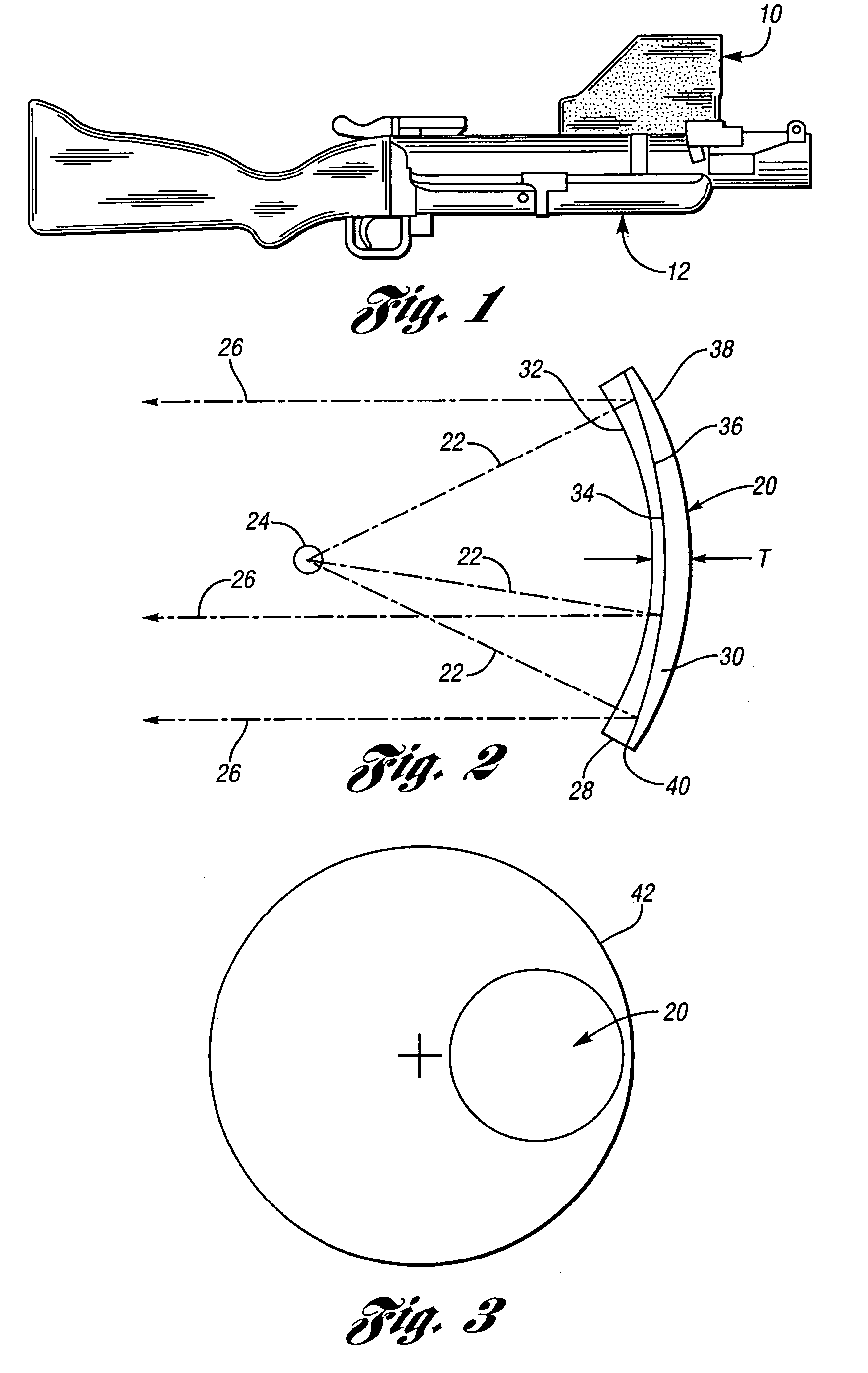
[0039]Referring now to FIG. 1, an aiming sight 10 in accordance with an embodiment of the present invention mounted on a firearm 12 is shown. Firearm 12 is intended to depict a low-velocity projectile firearm such as a shoulder-fired grenade launcher. It is to be appreciated that aiming sight 10 may be similarly mounted for use on other firearms, including, for example, firearms which launch air burst ammunition and rubber bullets.

[0040]Referring now to FIG. 2, a side view of a reflective collimator 20 of aiming sight 10 in accordance with an embodiment of the present invention is shown. Similar to a reflex or red-dot sight such as described in U.S. Pat. No. 3,905,708, collimator 20 collimates light beams 22 emanating from a light source such as a light emitting diode (LED) 24. Collimator 20 reflects light beams 22 to collimate them as collimated light beams 26.

[0041]In accordance with an embodiment of the present invention, collimator 20 includes front and rear spherical surface g...