Inlet partial blades for structural integrity and performance

a technology of partial blades and structural integrity, applied in the direction of waterborne vessels, wind motors with perpendicular air flow, machines/engines, etc., can solve the problems of reducing the efficiency of the pump, reduce the strain on the rotating seal member, and reduce the likelihood of rubbing

Active Publication Date: 2007-09-25
THE BOEING CO +1
View PDF26 Cites 24 Cited by
  • Summary
  • Abstract
  • Description
  • Claims
  • Application Information

AI Technical Summary

Benefits of technology

[0004]The present invention relates generally to methods and apparatus for conveying fluids. More particularly, the present invention relates to pumps (e.g., pumps capable of providing propellant to a rocket engine). An impeller in accordance with an exemplary embodiment of the present invention may advantageously include a plurality of inlet partials. The inlet partials may be positioned and dimensioned to reduce scalloping in a rotating seal member. When this is the case, strain in the rotating seal member is reduced. The likelihood that rubbing will occur between the rotating seal member and a stationary seal member is also reduced. Additionally, reduced scalloping allows for the use of relatively small seal clearances, thus boosting efficiency.
[0007]In some implementations, the opening is defined by an annular ring of the shroud. When this is the case, the at least one inlet partial may be capable of decreasing the radial deformation of the annular ring. In certain implementations, a second annular ring is disposed about the first annular ring so that a rotary seal is formed therebetween. A gap may, in some cases, be defined by the first annular ring and the second annular ring. The inlet partials supporting the first annular ring may be adapted so that the gap remains more constant when the first ring is rotating than would be the case if the first annular ring was not reinforced. The second annular ring may be formed by a pump casing in some implementations.
[0009]In one aspect of the present invention, the inlet partials are capable of precluding a change in the shape of the opening during rotation of the shroud. For example, the inlet partials may be capable of preventing the opening from assuming a non-circular shape. A deflection of the shroud during rotation of the shroud is advantageously smaller than a deflection occurring when the shroud is not supported by the inlet partials. The presence of the inlet partials may also cause the second shape to be more circular than would be the case without the inlet partials.

Problems solved by technology

High rotational speeds can cause the rotating member forming this seal to bow outwardly or scallop.
However, the larger seal clearances tend to reduce the efficiency of the pump.

Method used


Image

  • Inlet partial blades for structural integrity and performance
  • Inlet partial blades for structural integrity and performance
  • Inlet partial blades for structural integrity and performance

Examples


Embodiment Construction

[0020]The following detailed description should be read with reference to the drawings, in which like elements in different drawings are numbered identically. The drawings, which are not necessarily to scale, depict selected embodiments and are not intended to limit the scope of the invention. Examples of constructions, materials, dimensions, and manufacturing processes are provided for selected elements. All other elements employ that which is known to those of skill in the field of the invention. Those skilled in the art will recognize that many of the examples provided have suitable alternatives that can be utilized.

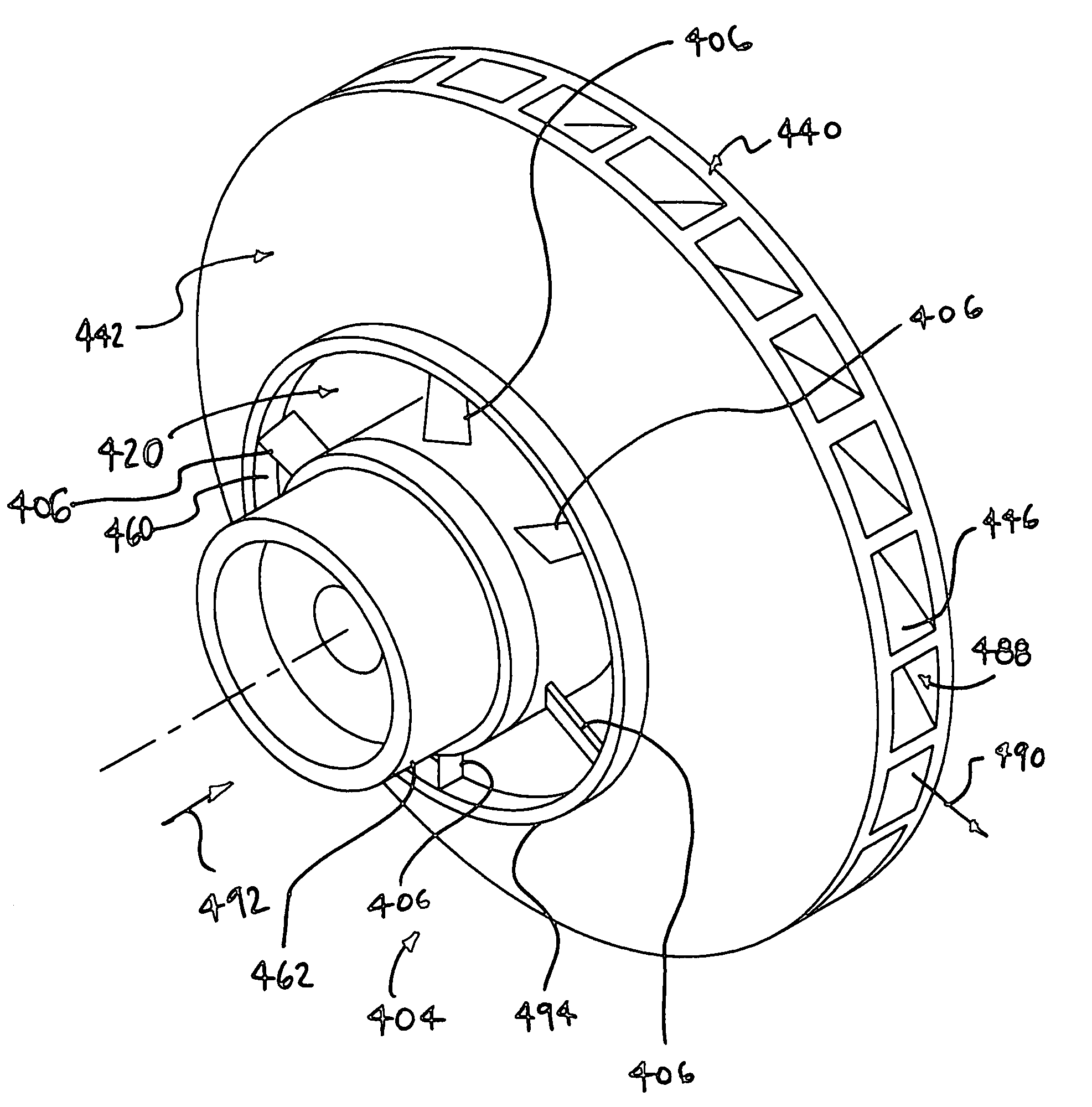
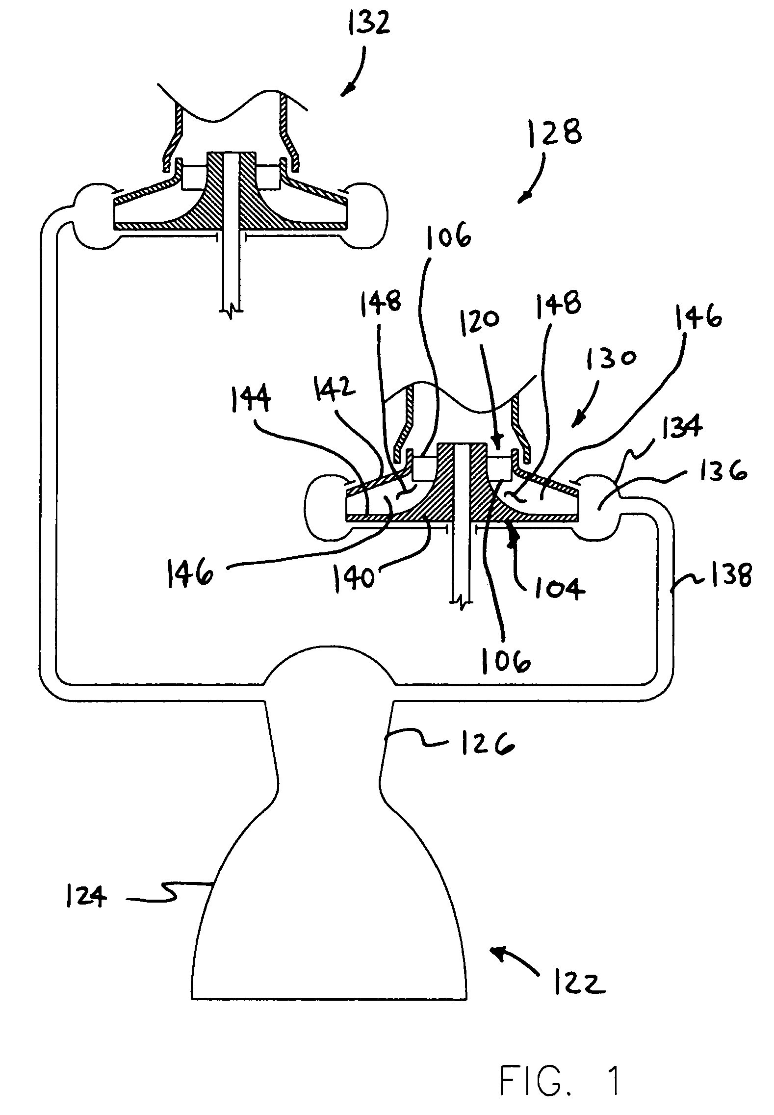
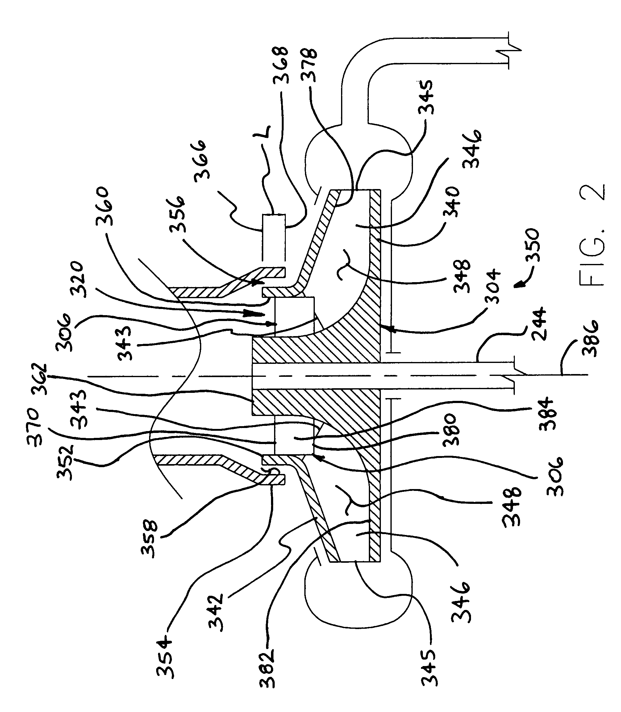
[0021]FIG. 1 is a simplified diagrammatic representation of a rocket engine 122. Rocket engine 122 of FIG. 1 includes a nozzle 124, a combustor 126 and a propellant supply system 128. In the embodiment of FIG. 1, propellant supply system 128 includes a first turbopump 130 and a second turbopump 132 that both fluidly communicate with combustor 126 of rocket engine 122....


PUM


Abstract

Methods and apparatus for conveying fluids (e.g., liquids, gases, and mixtures thereof) are disclosed. A turbopump in accordance with an exemplary implementation of the present invention comprises an impeller defining at least one flow channel and a shroud defining an opening communicating with the at least one flow channel. In certain advantageous implementations, at least one inlet partial of the impeller extends into the opening defined by the shroud. The at least one inlet partial may advantageously be capable of supporting the opening in the shroud. In some cases, the impeller may include a plurality of these inlet partials.

Description

FIELD OF THE INVENTION[0001]The present invention relates generally to methods and apparatus for conveying fluids (e.g., liquids, gases, and mixtures thereof). More particularly, the present invention relates to pumps (e.g., pumps capable of providing propellant to a rocket engine).BACKGROUND OF THE INVENTION[0002]Today, turbopumps are used in a wide variety of applications. One example of such an application is rocket propulsion systems. Many rocket propulsion systems include turbopumps as part of a propellant feed system. Turbopumps may be used, for example, to convey various fluids (e.g., fuels and oxidizers) to a combustor of the rocket engine. Turbopumps consist of turbine and pump components. The pump typically increases these incoming fluids to a higher pressure.[0003]The rotational seal is typically formed between a rotating portion of the pump (e.g., centrifugal pump impeller) and a stationary portion of the pump. High rotational speeds can cause the rotating member forming...

Claims


Application Information

Patent Timeline
Patent Type & Authority Patents(United States)
IPC IPC(8): F04D13/12F01D1/02F02K9/46F04D29/22
CPCF02K9/46F04D29/2294
Inventor WILLIAMS, MORGANCHEN, WEI-CHUNGHOANG, KHANH C.MILLER, JEFF H.
Owner THE BOEING CO
Why Eureka
Try Eureka