Power tool

a power tool and tool body technology, applied in the field of power tools, can solve the problems of difficult constant pressure on the tool, work surface being obscured, and difficulty in maintaining a constant pressure, so as to reduce the length of movement of the planer along the surface before the next blade contacts the surface, reduce the scalloping effect on the surface, and reduce the scalloping

Active Publication Date: 2006-07-04
POWER BOX
View PDF14 Cites 9 Cited by
  • Summary
  • Abstract
  • Description
  • Claims
  • Application Information

AI Technical Summary

Benefits of technology

[0022]This feature means that when the cylinder is rotating at normal speeds, then, in comparison with the conventional blade cylinders which have one or two straight blades, the length of movement of the planer along the surface before the next blade contacts the surface is reduced. This therefore means that the scalloping effect on the surface is reduced as the removal of material is achieved by a plurality of blade contacts rather than just one blade contact.
[0023]In a further embodiment, the blades provided on the cylinder are helically shaped in which case the cylinder includes two or more blades and provides the advantages of reduced scalloping. Preferably the planer is portable. In one embodiment the planer is a portable battery powered tool.

Problems solved by technology

This can be particularly difficult if the surface being planed is somewhat uneven.
Further, maintaining a constant pressure to the tool can be difficult, firstly due to the irregularities in the work surface, and secondly due to the position of the user relative to the tool.
This can result in the work surface being obscured, the wood shavings being deflected towards the user, or often the rotating blade cylinder can become jammed by wood shavings accumulating within the blade chamber of the assembly.
A problem with the conventional arrangement is that with the provision of one, or in some instances, two blades on the cylinder spaced 180 degrees apart, the size of chip removed and the spacing between the blades contacting the work piece surface, means that as the planer is moved along the surface a scalloping effect is created on the surface which does not provide the desired effect.
Furthermore, removal of the large chips which are created can be difficult.
However the positioning of the motor at the rear of the cylinder creates a problem with respect to the removal of the chips of wood and other debris created by the cutting action of the blade on the cylinder.
The problem is that because of the motor position, the chips cannot easily be discarded from the rear of the planer which would be the natural flow of the same and so, instead, relatively complex chip removal channels are required to be formed in the housing along which the chips and debris are required to pass prior to leaving the planer housing and which typically are required to be fan assisted.
The complexity of the channels can mean that the same are extremely prone to blockage by the chips which, in turn, prevents use or efficient use of the planer.
Furthermore, to accommodate the removal channels, the housing can be required to be increased in size and may also cause the chips and debris to exit the housing at a location and / or side of the housing which is inconvenient to the user.
In this patent, the motor is still mounted to the rear of the blade cylinder and so it is not possible to move the channels past the drive means motor as it will increase the width of the planer body.

Method used


Image

  • Power tool
  • Power tool
  • Power tool

Examples


Embodiment Construction

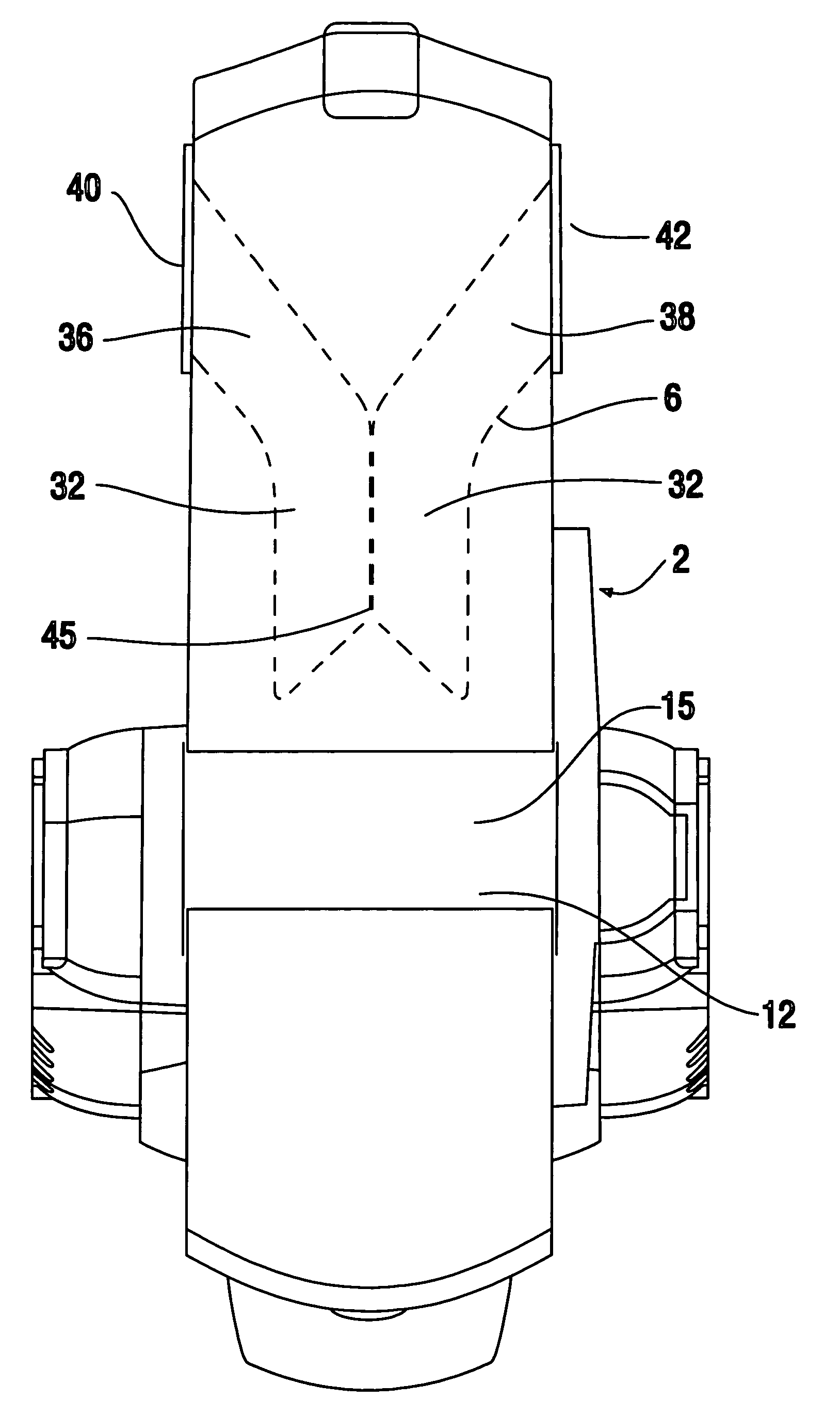
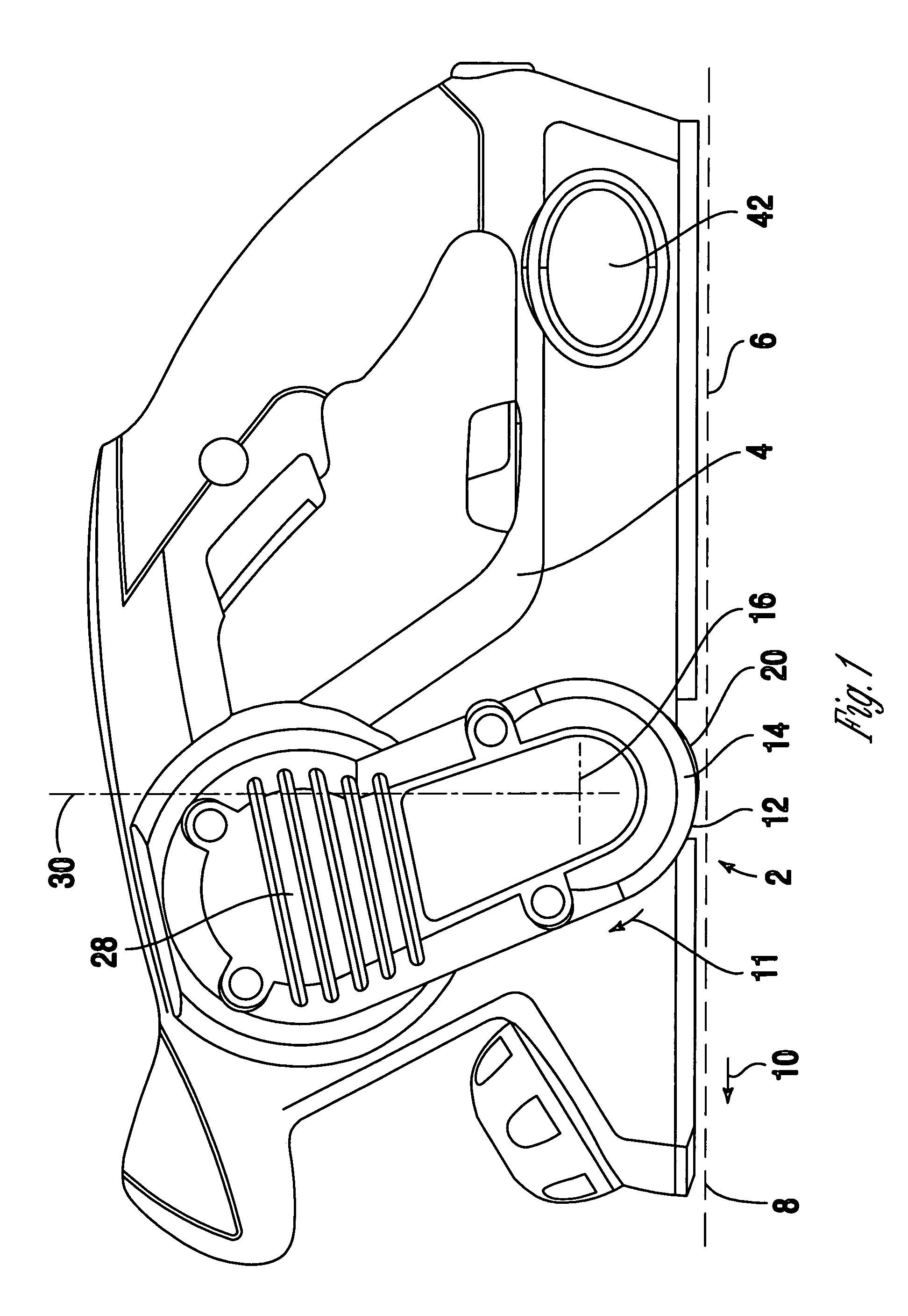
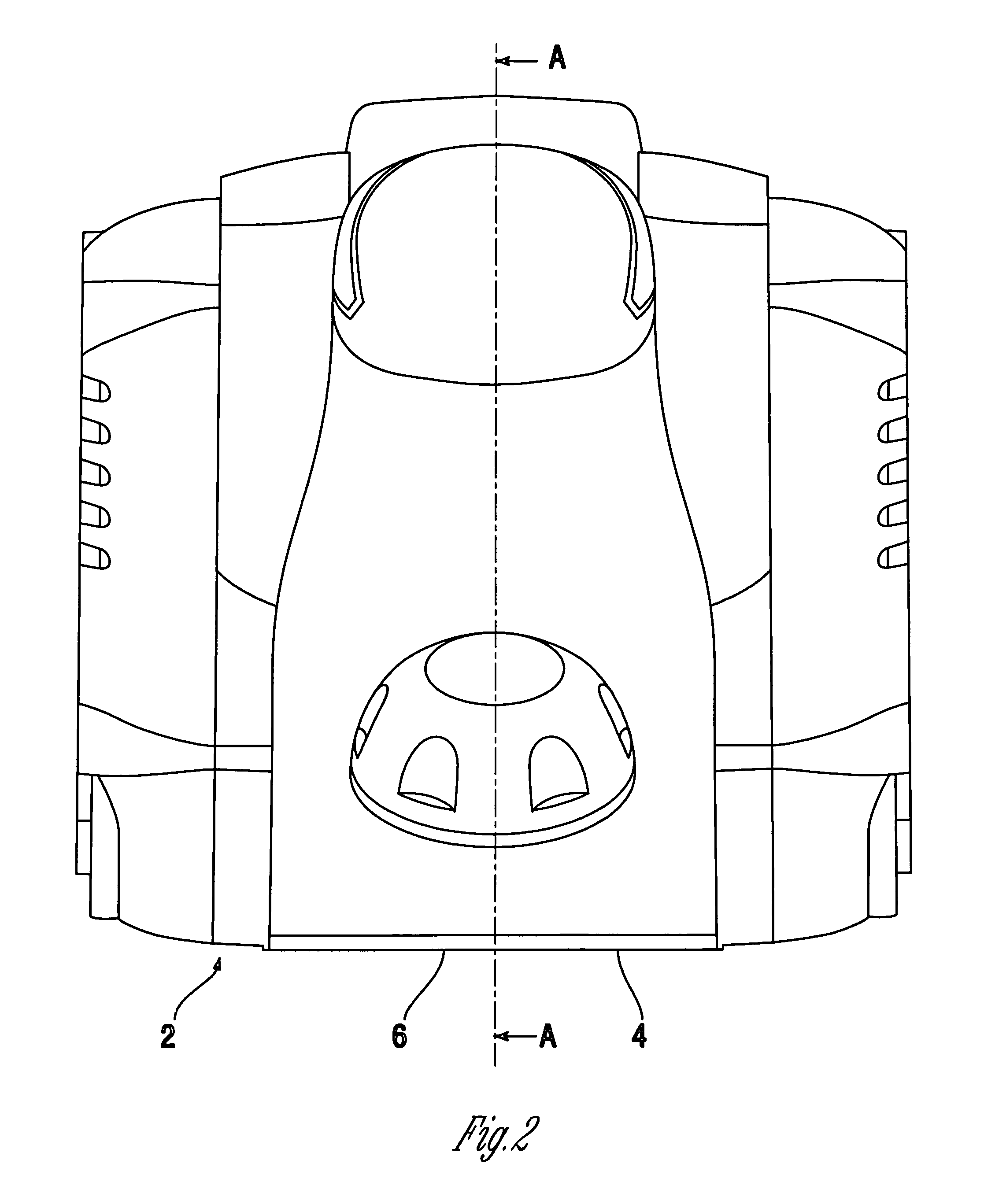
[0035]Referring firstly to FIGS. 1–5 there is illustrated a planer 2 in accordance with the invention.

[0036]The planer comprises a housing 4 with a planing surface 6 which is provided to be moved along the surface of a workpiece to be planed 8 (shown in broken lines in FIG. 1) in the direction 10. The planing surface includes an aperture 12 and positioned above said aperture, within the body housing 4 is a blade assembly including a blade cylinder 14 in a blade chamber 15. The cylinder is provided to rotate about an axis of rotation 16 in the direction indicated by arrow 11 and is positioned such that the periphery surface 20 of the cylinder passes through the aperture 12 and exposes blades 22, 24, 26, shown in FIG. 6, mounted at spaced locations on the cylinder as shown, to the surface 8 to be planed. The rotation and exposure of the blades causes the removal of wooden chips and shavings from the surface to provide the planing effect.

[0037]The cylinder rotation is driven by drive m...


PUM


Abstract

A planer including a housing having a base planing surface for contacting a workpiece, a rotatable blade cylinder located within said housing and including more than one cutting blade for engaging with and planing the work piece. A drive means is associated with the blade cylinder and operable to cause rotation of the blade cylinder. The drive means is located within the housing, above the axis of rotation of the blade cylinder and a chip an debris removal channel passes from the location of the cylinder to the rear end of the planer.

Description

BACKGROUND OF THE INVENTION[0001]The invention to which this application relates is to a power tool, powered by any suitable source but most typically via a main electric or battery supply, which is used in the removal of material from a surface of a typically wooden article. This type of product is most typically referred to as a planer and that is the term used herein.[0002]The provision of powered planer tools is well known. Planers are used in wood working to plane or smooth an uneven surface and may also include the removal of paint layers. The planer includes a blade assembly including a blade holding cylinder which is rotated at high speed. As the planer is moved across the work surface, raised parts of the uneven surface are shaved by the rotating blades which protrude through an aperture in the planing surface of the planar, the planing surface of the planar contacting the work surface and acting as a level and guide.[0003]In order to obtain a smooth finished surface, it is...

Claims


Application Information

Patent Timeline
Patent Type & Authority Patents(United States)
IPC IPC(8): B27C1/02B27C1/10B23Q11/00
CPCB27C1/10B23Q11/005
Inventor PARK, KEITHHOSKING, PETER J.
Owner POWER BOX
Why Eureka
Try Eureka