Cutting insert for chip removing machining

a cutting insert and chip technology, applied in the direction of cutting inserts, shaping cutters, manufacturing tools, etc., can solve the problems of shortening the service life, vibration and detrimental heat generation, and deteriorating the service life and performance of the inser

Inactive Publication Date: 2004-04-06
SANDVIK INTELLECTUAL PROPERTY AB
View PDF25 Cites 55 Cited by
  • Summary
  • Abstract
  • Description
  • Claims
  • Application Information

AI Technical Summary

Benefits of technology

The present invention aims at obviating the above-mentioned disadvantages of previously known cutting inserts and at providing an improved cutting insert. Therefore, a primary aim of the invention in a first aspect is to improve the cutting geometry surface adjacent to the operatively active cutting edge of the cutting insert, more precisely with the purpose of minimizing the risk of heat concentrations and crack formations in the material in the surface zone of the cutting insert. Another aim of the invention is to provide a cutting insert that generally guarantees an improved surface finish of the machined surface of a workpiece. In the embodiment thereof as turning insert, this possibility should for instance be utilized for radically increased feeding with a retained or even improved surface finish. In an analogous way, the invention should be able to be utilized for general performance increase of cutting inserts having a surface smoothening edge segment also for other machining techniques than just turning, such as milling, drilling, broaching or the like.

Problems solved by technology

In said tumblings and ridges, respectively, protruding high up from the bottom regions of the cutting geometry surface, heat concentrations occur, which inter alia lead to crack formations in the cutting insert, and thereby shortening the service life thereof.
However, too large a nose radius may cause vibrations and detrimental generation of heat.
A disadvantage of a small nose radius, however, is that the wear of the cutting insert is hastened, whereby the service life and performance thereof are deteriorated.
An annoying circumstance in regards of the surface finish in previously known cutting inserts is that the position of the actual tangent point along the surface smoothening edge segment has not been able to be predetermined in a reliable way.
Theoretically, it is feasible, per se, to enable high feedings with straight smoothening edge segments, but in practice this way is objectionable so far that straight edge segments with a smoothening function involves large radial cutting forces with the ensuing risk of vibrations and high generation of heat.

Method used


Image

  • Cutting insert for chip removing machining
  • Cutting insert for chip removing machining
  • Cutting insert for chip removing machining

Examples


Embodiment Construction

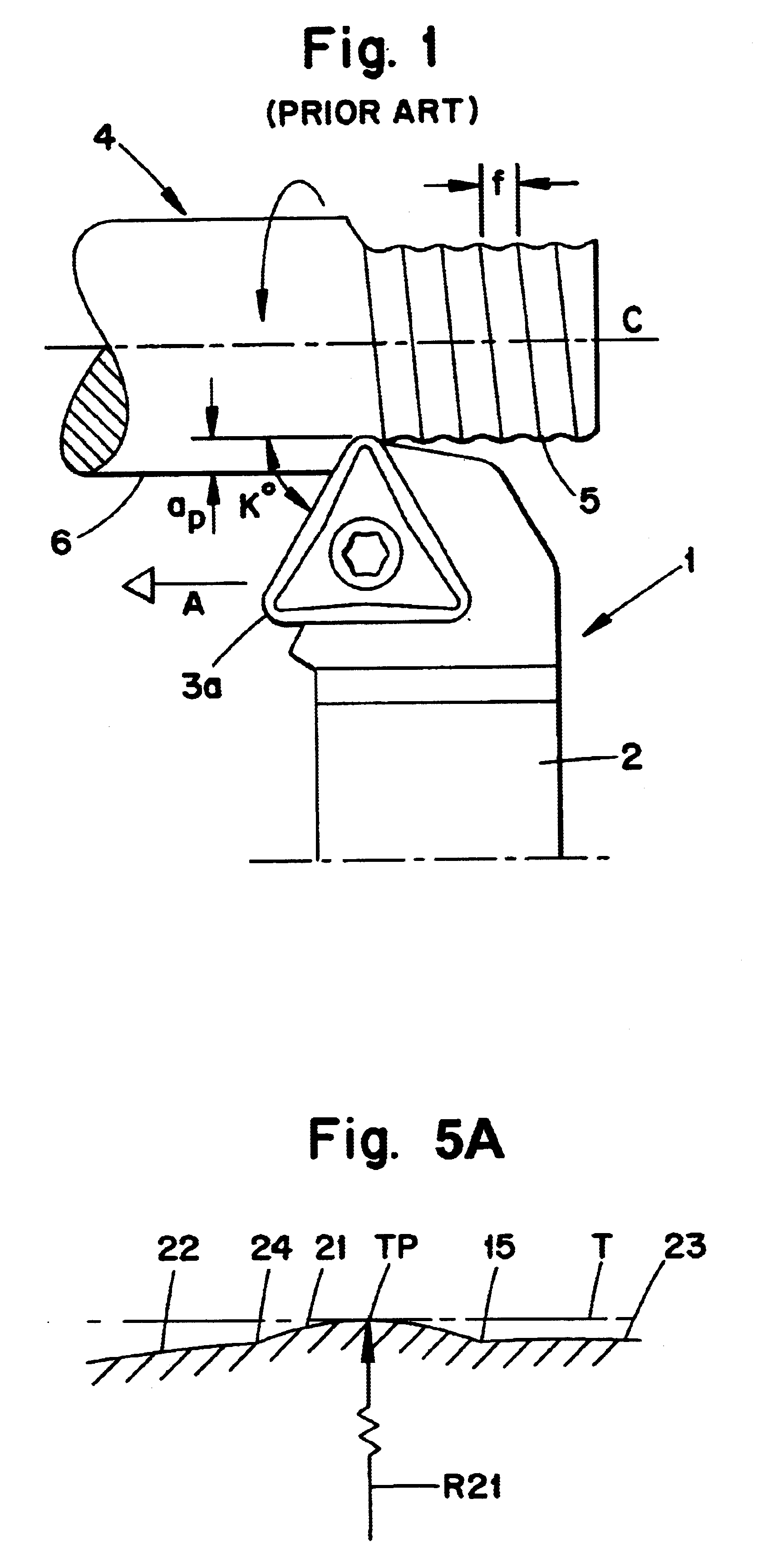
In FIG. 1, a turning tool is shown schematically during machining of a workpiece. The machining in this case consists of longitudinal turning. The tool is in its entirety designated 1 and includes a bar or holder 2, as well as a replaceable cutting insert 3a. The workpiece 4 rotatable around a geometric axis C. A machined, cylindrical surface 5 on the workpiece typically has wave formations shown in drastically exaggerated scale in FIG. 1, which detract from the surface finish. The distance between the tops of these wave formations is a function of the feeding f of the cutting insert 3a, which is measured in mm / revolution. Furthermore, a.sub.p designates the cutting depth that constitutes the radial difference between the machined surface 5 and the unmachined surface 6 as measured perpendicularly to the feeding direction of the tool (see the arrow A). The side angle K.degree. is the angle between the main cutting edge and the feeding direction of the cutting insert.

Reference is now ...


PUM

PropertyMeasurementUnit
angleaaaaaaaaaa
angleaaaaaaaaaa
angleaaaaaaaaaa

Abstract

A cutting insert, intended for chip removing machining includes a cutting geometry surface having a cutting edge from which extends a primary chamfer that transforms into a chip removing surface. The chip removing surface is inclined in a inwards / downwards direction in order to permit sinking of a chip being formed, and transforms into a deflection surface arranged to initiate deflection of the chip from the cutting insert. The angle of inclination of the chip removing surface does not exceed 18°. The level difference in elevation between the primary chamfer and the chip deflection surface amounts to maximally 0.20 mm.

Description

This application claims priority under 35 U.S.C. .sctn.119 to patent application Ser. No. 0103255-6 filed in Sweden on Oct. 1, 2001, the entire content of which is hereby incorporated by reference.This invention relates to a cutting insert, intended for chip removing machining, of the type that comprises a body that is delimited by on one hand two opposite, first and second surfaces, which in the operative state of the cutting insert form an actively chip removing top surface and an inactive bottom surface, respectively, and on the other hand at least one side surface serving as a flank surface, which extends between said first and second surfaces. A cutting edge is formed between the flank surface and at least one of said first and second surfaces, in connection with which a cutting geometry surface extends, which is generally parallel to an imaginary reference plane through the cutting body. The cutting geometry surface, counted from the cutting edge, includes a primary chamfer wh...

Claims


Application Information

Patent Timeline
Patent Type & Authority Patents(United States)
IPC IPC(8): B23B27/14
CPCB23B27/141B23B2200/0447B23B2200/0461B23B2200/0476B23B2200/082Y10T407/235B23B2200/201B23B2200/323Y10T407/245Y10T407/23Y10T407/24B23B2200/087B23B27/22
Inventor WIMAN, JORGENLOF, RONNIE
Owner SANDVIK INTELLECTUAL PROPERTY AB
Why Eureka
Try Eureka