Vane or blade for an axial flow compressor

a compressor and axial flow technology, applied in the direction of liquid fuel engines, marine propulsion, vessel construction, etc., can solve the problems of reducing limiting the pressure rise capability of the compressor, and increasing the stall margin usually, so as to reduce the loss of three-dimensional, improve the efficiency, and improve the performance of the compressor

Active Publication Date: 2011-04-07
SIEMENS ENERGY GLOBAL GMBH & CO KG
View PDF2 Cites 60 Cited by
  • Summary
  • Abstract
  • Description
  • Claims
  • Application Information

AI Technical Summary

Benefits of technology

[0015]In the current invention 3D CFD code has been used to set the leading edge and trailing edge blade angles. The code has also been used to customise the airfoil profile shape and the stacking of the airfoil sections. Thereby, losses have been minimised and flow ranges have been improved. The increased leading edge blade angles close to the hub and close to the casing of the compressor help to reduce large positive incidences induced by viscous three-dimensional flows in these regions and hence help to reduce blade surface boundary layer thickness and flow separation towards the trailing edge. The increased blade angles and reduced incidences also help to reduce tip leakage flows in the casing region of rotor blades and in the hub region of cantilevered stator vanes. The reduced leading edge blade angles in the mid-span region help to maintain an adequate choke margin. In addition, the leading edge stacking on a radial straight line helps to produce more compound (curved) lean towards a trailing edge with a pressure surface facing the hub and casing. This helps to relieve blade loading in the end wall regions and hence to reduce tip leakage flows where there is a tip clearance, and to reduce suction surface-end wall corner flow separations, and thus helps to reduce three-dimensional loss and to improve stall margin.
[0017]The mentioned trailing edge angle design helps to relieve local blade or vane loading and hence helps to reduce suction surface end wall corner flow separation in the end wall regions of the blade or vane, i.e. in the hub region or the casing region.
[0018]For cantilevered stator vanes the trailing edge blade angles in the hub region can be kept similar to conventional stator vanes as the tip leakage flow helps to relieve the loading in these regions. In addition, the trailing edge blade angles of rotor blades in the casing region can be kept similar to conventional design since also in this case tip leakage flow helps to relieve the loading in the casing regions.
[0019]The trailing edge blade angles in mid-span region can be kept similar to conventional designs if the change in trailing edge blade angle with respect to the conventional design is small in the end wall regions or reduced if the trailing edge blade angles are increased in the end wall regions.
[0021]The disclosed treatments of the trailing edge blade angles in the mid-span region helps to maintain the overall loading of the rotor blades or stator vanes relative to the conventional rotor blades or stator vanes.
[0022]An inventive axial flow compressor comprises inventive blades and / or vanes. With the inventive blades and / or vanes the performance of the compressor can be improved due to reduced three-dimensional losses, improved efficiency, and an increased stall margin.

Problems solved by technology

Three-dimensional loss reduction and improving efficiency and stall margin of axial flow compressors are still technical issues in designing compressor blades and vanes.
Three-dimensional losses limit the pressure rise capability of the compressor.
Such losses result e.g. from flow separation in suction surface, endwall corners, leakage around the tip, and secondary flow regions.
Optimising efficiency and stall margin always involves a compromise since increasing efficiency usually reduces stall margins and increasing stall margins usually reduces efficiency.

Method used


Image

  • Vane or blade for an axial flow compressor
  • Vane or blade for an axial flow compressor
  • Vane or blade for an axial flow compressor

Examples


Embodiment Construction

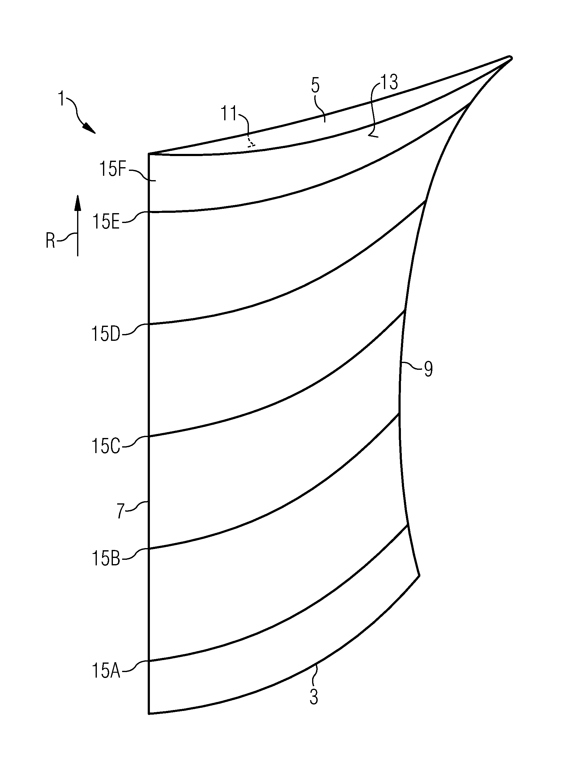
[0031]An airfoil using the features of the invention is shown in FIG. 1 in a three-dimensional view. The features noticeable in FIG. 1 can, in general, be used for the airfoils of compressor rotor blades as well as the airfoils of compressor stator vanes.

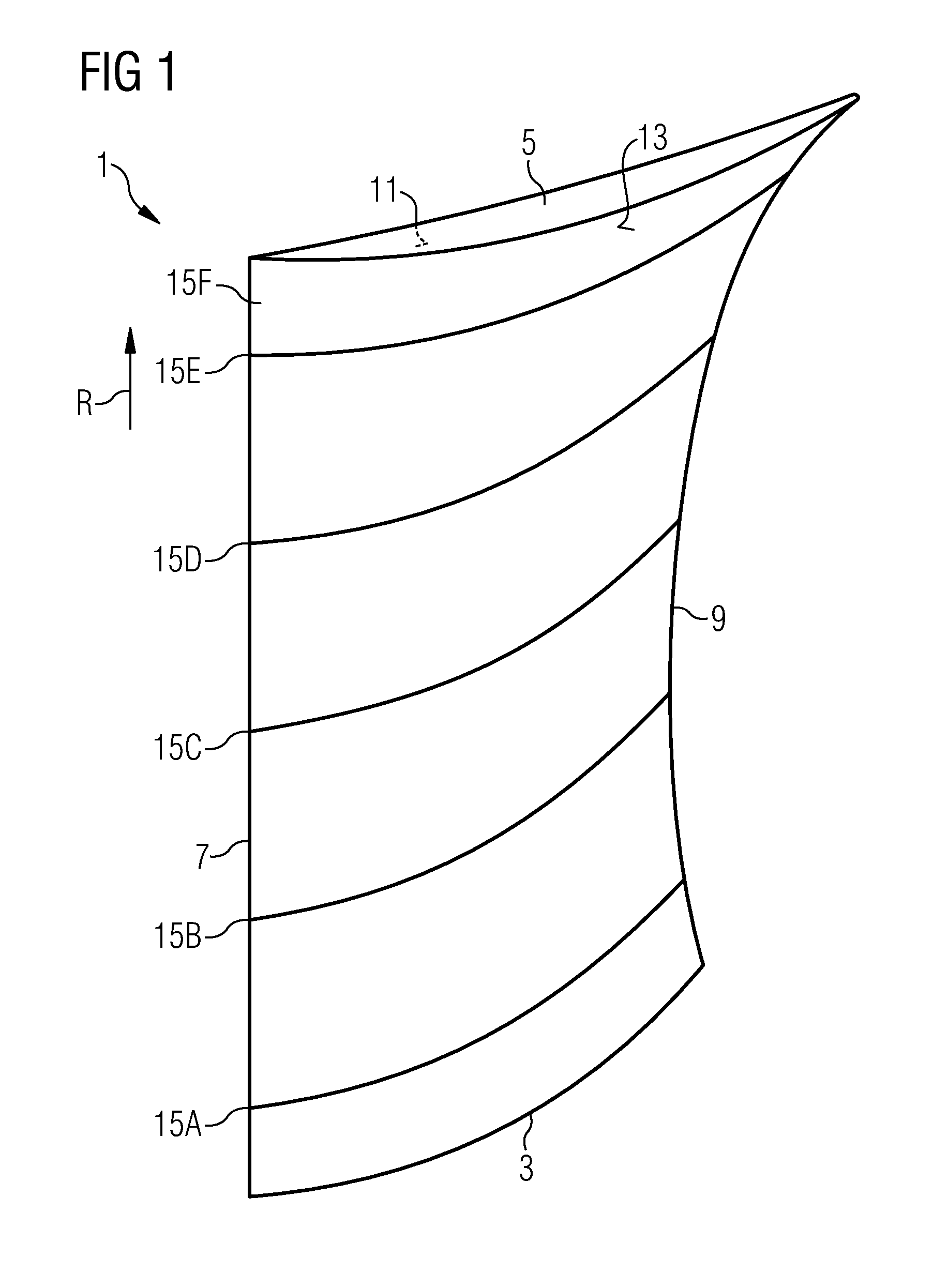
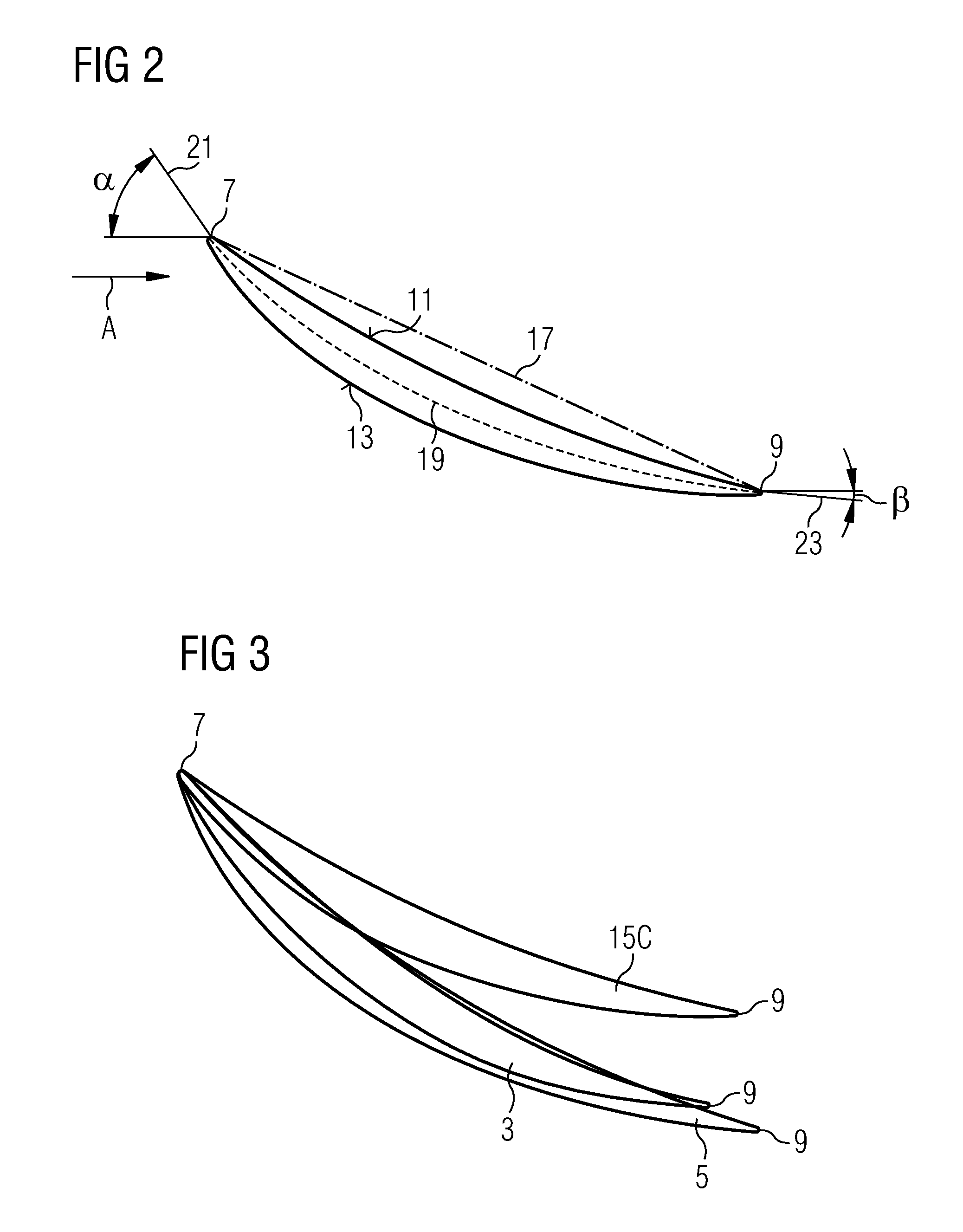
[0032]The airfoil 1 comprises a hub section 3 which shows towards the rotor when the airfoil is incorporated in a compressor, and a casing section 5 which shows towards the compressor casing when the airfoil 1 is incorporated into a compressor. It further comprises a leading edge 7 and a trailing edge 9 which both extend from the hub section 3 to the casing section 5. While the leading edge follows a straight line extending in radial direction R of the compressor the trailing edge 9 is curved with respect to the radial direction of the compressor. The trailing edge 9 may, in addition, be curved with respect to the axial direction of the compressor, too. Between the leading edge 7 and the trailing edge 9 extends a pressure surface 11...


PUM


Abstract

A compressor vane or compressor blade is provided. The axial flow compressor includes an axial direction, a radial direction, a compressor hub and a compressor casing. The vane or blade includes an airfoil with airfoil sections having a span, a chamber line and a leading edge at which the chamber line includes a leading edge blade angle with the axial direction of the compressor and a trailing edge at which the chamber line includes a trailing edge blade angle with the axial direction of the compressor. The airfoil sections are stacked at the leading edge on a straight line extending along a radial direction of the compressor from the compressor hub towards a compressor casing and in that the leading edge angles of the airfoil sections vary along the span and are larger for airfoil sections close to the hub and close to the wall than for mid-span airfoil sections.

Description

CROSS REFERENCE TO RELATED APPLICATIONS[0001]This application is the US National Stage of International Application No. PCT / EP2009 / 054025, filed Apr. 3, 2009 and claims the benefit thereof. The International Application claims the benefits of European Patent Office application No. 08010816.0 EP filed Jun. 13, 2008. All of the applications are incorporated by reference herein in their entirety.FIELD OF INVENTION[0002]The present invention relates to compressor vanes or blades for axial flow compressors and to an axial flow compressor.BACKGROUND OF INVENTION[0003]Three-dimensional loss reduction and improving efficiency and stall margin of axial flow compressors are still technical issues in designing compressor blades and vanes. Three-dimensional losses limit the pressure rise capability of the compressor. Such losses result e.g. from flow separation in suction surface, endwall corners, leakage around the tip, and secondary flow regions. Optimising efficiency and stall margin always ...

Claims


Application Information

Patent Timeline
Patent Type & Authority Applications(United States)
IPC IPC(8): F03B3/12
CPCF04D29/324F05D2250/70F04D29/544Y02T50/60
Inventor LI, YAN SHENG
Owner SIEMENS ENERGY GLOBAL GMBH & CO KG
Why Eureka
Try Eureka