
Load pressure self-feedback flow regulating valve

A flow control valve, load pressure technology, applied in the direction of fluid pressure actuation device, elastic suspension, suspension, etc., can solve problems such as adjustment of height error lifting stability, hydraulic locking and internal leakage

Pending Publication Date: 2021-06-25
CHINA NORTH VEHICLE RES INST
View PDF12 Cites 0 Cited by
  • Summary
  • Abstract
  • Description
  • Claims
  • Application Information

AI Technical Summary

Problems solved by technology

[0002] With the continuous improvement of vehicle capacity, driving stability, safety and comfort requirements in the production process, especially for storage and transportation equipment with large load changes, an additional set of vehicle posture adjustment system is required in addition to oil and gas springs Through the control of the attitude of the car body, the consistency of the ground clearance of the car under the empty and full load state and the passability of the uneven road surface can be ensured, and the dangerous phenomena such as rollover of the car under special operating conditions can be effectively avoided, so as to meet the requirements of the car for the whole car. Road adaptability requirements, but because it belongs to the high-pressure working system, and there are technical problems such as hydraulic lock internal leakage, adjustment height error, and lifting stability, it is particularly necessary to develop a high-stability vehicle attitude adjustment system

Method used


Image

  • Load pressure self-feedback flow regulating valve
  • Load pressure self-feedback flow regulating valve
  • Load pressure self-feedback flow regulating valve

Examples


Embodiment Construction

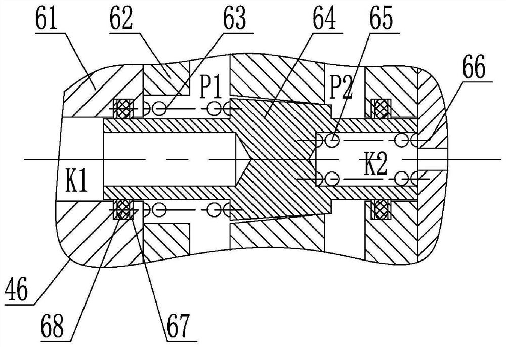
[0027] The present invention will be described in detail below with reference to the accompanying drawings and examples.

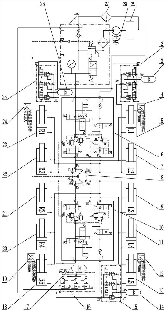
[0028] The invention provides a load pressure self-feedback flow regulating valve, which is applied in a load pressure self-feedback car posture regulating valve group of a car posture regulating system.

[0029] figure 1It is the structure and principle diagram of the load pressure self-feedback flow regulating valve. All load pressure self-feedback flow regulating valves in the system have the same structure. The load pressure self-feedback flow regulating valve consists of an end cover 61, a valve body 62, a guide spring 63, a valve core 64, a return spring 65, a top cover 66, and a protection ring 67. And O-ring 68 components. The valve can be an external independent flow regulating device, or it can be embedded in the valve group to become a component of the valve group. The valve core 64 is assembled in the center hole of the valve body 62, and ad...


PUM


Abstract

The invention discloses a load pressure self-feedback flow regulating valve, and belongs to the application field of hydraulic machinery and motor vehicles. The self-feedback flow regulating valve is provided with four oil ports of a K1 control end, a K2 control end, a P1 output end and a P2 input end, and the P1 output end and the P2 input end are connected with an oil inlet and an oil outlet in a control oil circuit separately; K1 and K2 are two external pressure control ends, and the K2 end and a valve core spring pressure reset are in the same direction; the K1 end is used for controlling the flow regulating valve to tend to flow reduction; the K2 end is used for controlling the flow regulating valve to tend to flow increase, and in use, the K1 end and the K2 end are connected with the corresponding load pressure according to the requirements separately; and the opening degree of the flow valve is controlled through load pressure, and load self-feedback control is formed. According to the self-feedback flow regulating valve, the opening degree of the valve core can be automatically adjusted through the pressure feedback control end, and the purpose of flow regulation is achieved; and compared with a traditional electromagnetic proportional throttle valve, the self-feedback flow regulating valve has the advantages of large flow control range, simple and compact structure and convenient integration in a hydraulic system.

Description

technical field [0001] The invention relates to a load pressure self-feedback flow regulating valve, which belongs to the application field of hydraulic machinery and motor vehicles. Background technique [0002] With the continuous improvement of vehicle capacity, driving stability, safety and comfort requirements in the production process, especially for storage and transportation equipment with large load changes, an additional set of vehicle posture adjustment system is required in addition to oil and gas springs Through the control of the attitude of the car body, the consistency of the ground clearance of the car under the empty and full load state and the passability of the uneven road surface can be ensured, and the dangerous phenomena such as rollover of the car under special operating conditions can be effectively avoided, so as to meet the requirements of the car for the whole car. Road adaptability requirements, but because it is a high-pressure working system, a...

Claims


Application Information

Patent Timeline
IPC IPC(8): F15B13/02B60G17/08
CPCF15B13/02B60G17/08
Inventor 郑冠慧陈轶杰张亚峰毛明黄龙高晓东徐梦岩张旭万义强韩小玲代健健李宝强
Owner CHINA NORTH VEHICLE RES INST
Learn More