Integrated gas dispenser detection device through standard meter method

A detection device, a technology of standard table method, applied in mechanical equipment, container filling method, container discharge method, etc., can solve the problems of inability to verify the gas dispenser in the laboratory, narrow flow device range, verification and other problems, and achieve easy operation and reliability. Controllability and accuracy, avoid inconvenience of operation, enhance the effect of flow range

Inactive Publication Date: 2013-06-12
CHONGQING ACAD OF METROLOGY & QUALITY INST +1
View PDF4 Cites 0 Cited by
  • Summary
  • Abstract
  • Description
  • Claims
  • Application Information

AI Technical Summary

Problems solved by technology

[0003] At present, there are some problems in the verification of gas dispensers and their devices in China: (1) At present, there are many types of on-site verification devices for gas dispensers in China. Narrow, with a maximum flow rate of 20kg / min, it is impossible to verify the large flow gas filling machine (commonly known as the gas filling column, the maximum flow rate can reach 50kg / min)
(2) At the same time, most metrological verification institutions are still unable to carry out laboratory verification of gas filling machines
Only a few have relevant verification devices, and the verification media used are various, some use compressed air as the medium for detection, and some use water as the medium, the measurement accuracy of the verification device cannot be guaranteed
(3) The connection method of a portable notebook computer plus a verification device is adopted. This connection method requires an external power supply, and the power supply itself brings great unsafe factors to the on-site verification due to problems such as the site and the line.

Method used


Image

  • Integrated gas dispenser detection device through standard meter method

Examples


Embodiment Construction

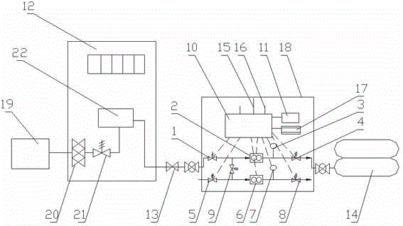
[0023] The present invention will be described in further detail below in conjunction with the accompanying drawings and specific embodiments.

[0024] Such as figure 1 As shown, the integrated standard table method gas filling machine detection device includes gas filling machine inlet valve 1, flow meter I2, gas filling machine pipeline pressure sensor 3, gas filling machine outlet valve 4, gas filling column inlet valve 5, Flow meter Ⅱ6, pressure sensor 7 of gas filling column pipeline, gas filling column outlet valve 8, intake switching valve 9, embedded ARM main board 10, LCD display 11, box body 18 and lithium battery with external charging power supply (in the figure not shown). In this embodiment, flowmeter I2 and flowmeter II6 use CNG050 mass flowmeters. The lithium battery is placed in an explosion-proof box, explosion-proof box, gas dispenser inlet valve 1, flow meter Ⅰ2, gas dispenser pipeline pressure sensor 3, gas dispenser outlet valve 4, gas column inlet valv...


PUM


Abstract

The invention discloses an integrated gas dispenser detection device through a standard meter method; the device comprises a gas disperser air inlet valve, a flowmeter I, a gas disperser pipeline pressure sensor, a gas disperser air outlet valve, a gas dispersing column air inlet valve, a flowmeter II, a gas dispersing column pipeline pressure sensor, a gas dispersing column air outlet valve, an embedded ARM (Advanced RISC Machine) mainboard and the like; the gas disperser air inlet valve, the flowmeter I and the gas disperser air outlet valve are connected in turn through a pipeline; the gasdispersing column air inlet valve, the flowmeter II and the gas dispersing column air outlet valve are connected in turn through a pipeline; and the flowmeter I, the flowmeter II, the gas disperser pipeline pressure sensor and the gas dispersing column pipeline pressure sensor are connected with the embedded ARM mainboard through a signal line. The device disclosed by the invention is used for solving the potential safety hazard caused by the current gas disperser field detection device and solving metering detection of a gas dispersing column and a gas discharging column; in addition, the embedded ARM mainboard is adopted, and the device is connected to a liquid crystal display screen, a keyboard and the like; therefore, operations, such as a detection step, a control process, a detection result and the like, are completely realized on the device.

Description

technical field [0001] The invention relates to a metering detection device, in particular to a gas dispenser detection device. Background technique [0002] At present, compressed natural gas (CNG) is the most ideal alternative energy for vehicles. It is an important basic energy and natural industry in the development of the national economy, and it is a priority development focus in the economic development strategies of countries around the world. As an advanced productive force and basic industry, it is closely related to social economic and social development, not only related to the economic security of the country, but also closely related to people's daily life and social stability. With the development of my country's economy, the demand for compressed natural gas continues to expand, and its application technology is becoming more and more mature. Compressed natural gas, with its advantages of low cost, high benefit, no pollution, and safe and convenient use, is ...

Claims


Application Information

Patent Timeline
Patent Type & Authority Patents(China)
IPC IPC(8): F17C13/02
Inventor 王硕张泽宏戚宁武李沿飞张松杨其华张俊
Owner CHONGQING ACAD OF METROLOGY & QUALITY INST
Why Eureka
Try Eureka