Flowmeter and calorimeter asynchronous metering and detecting method and flowmeter and calorimeter asynchronous metering and detecting system based on communication

A technology of measurement and detection and flowmeter, which is applied in the measurement of heat, calorimeter, liquid/fluid solid measurement, etc., can solve the problems that the detection technology cannot meet the detection requirements, does not have high-response pulse signal output, and is difficult to adapt to.

Inactive Publication Date: 2013-01-23
ZHEJIANG MEASUREMENT SCI RES INST
View PDF4 Cites 4 Cited by
  • Summary
  • Abstract
  • Description
  • Claims
  • Application Information

AI Technical Summary

Problems solved by technology

Many instruments often do not have high-response pulse signal output, and hope to improve efficiency by shortening the detection time, so this detection technology based on synchronous measurement is difficult to adapt
[0007] With the development of electronic technology and computer technology, more and more instruments use digital communication signals as output signals, and the detection technology based on synchronization cannot meet the detection requirements

Method used


Image

  • Flowmeter and calorimeter asynchronous metering and detecting method and flowmeter and calorimeter asynchronous metering and detecting system based on communication
  • Flowmeter and calorimeter asynchronous metering and detecting method and flowmeter and calorimeter asynchronous metering and detecting system based on communication
  • Flowmeter and calorimeter asynchronous metering and detecting method and flowmeter and calorimeter asynchronous metering and detecting system based on communication

Examples


Embodiment 1

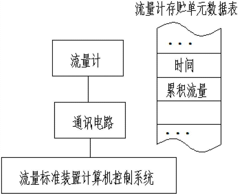
[0036] Reference attached figure 1 .

[0037] The object of this embodiment is a flow meter, and the implementation process is described as follows.

[0038] The communication-based non-synchronized measurement and detection method for flow meters and heat meters of the present invention includes the following steps:

[0039] Step 1. Detect the flow meter and heat meter to be checked, and the microprocessor of the flow and heat signal measured by the sensor is processed by signal and data calculation to obtain the accumulated flow and accumulated heat;

[0040] Step 2: When the microprocessor stores the accumulated flow rate and / or accumulated heat data in the data storage unit, it also stores the time data collected to the internal clock of the microprocessor at this moment in the data storage unit; For flow meters, the cumulative flow and time form a set of one-to-one correspondence data; for heat meters, the cumulative flow, cumulative heat and time form a set of one-to-one corresp...

Embodiment 2

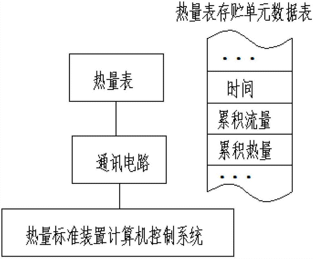
[0048] Reference attached figure 2 .

[0049] The main difference between this embodiment and the first embodiment is that the meter object is different. The meter targeted by this embodiment is a heat meter.

[0050] The implementation process is described as follows.

[0051] The communication-based non-synchronized measurement and detection method for flow meters and heat meters of the present invention includes the following steps:

[0052] Step 1. Detect the flow meter and heat meter to be checked, and the microprocessor of the flow and heat signal measured by the sensor is processed by signal and data calculation to obtain the accumulated flow and accumulated heat;

[0053] Step 2: When the microprocessor stores the accumulated flow rate and / or accumulated heat data in the data storage unit, it also stores the time data collected to the internal clock of the microprocessor at this moment in the data storage unit; For flow meters, the cumulative flow and time form a set of one-t...

Embodiment 3

[0062] This embodiment describes a system using the method of the present invention.

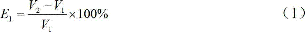
[0063] A communication-based non-synchronized measurement and detection system for flow meters and heat meters, including a standard device computer control system, and sensors for measuring flow signals and heat signals of flow meters and heat meters, characterized in that: the sensors are connected to a microprocessor The microprocessor includes an accumulation unit that accumulates the flow signal and the heat signal to obtain the accumulated flow and accumulated heat, and collects the accumulated flow and accumulated heat with this time from the internal clock of the microprocessor A data storage unit and a communication unit that store time data together; the communication unit is connected to the computer of the standard device computer control system, and the flow rate measurement error E is set in the computer 1 And calorie measurement error E 2 The calculation unit is as follows:

[0064...


PUM


Abstract

The invention provides a flowmeter and calorimeter asynchronous metering and detecting technology and a flowmeter and calorimeter asynchronous metering and detecting system based on communication. The flowmeter and calorimeter asynchronous metering and detecting technology comprises the following steps of: (1) storing accumulative flow and (or) accumulative heat, together with current time data, into a data storage unit in a grouped manner by microprocessors of meters (including a flowmeter and a calorimeter); (2) transmitting grouped data into a computer control system of a standard device through a communication circuit (which is wired or wireless) by the microprocessors, and generating standard accumulative flow and (or) accumulative heat and time values by the standard device under the control of the computer control system; and (3) calculating metered and detected results by the computer control system of the standard device according to a preset computational formula. The system comprises the computer control system of the standard device, a sensor and the microprocessors.

Description

Technical field [0001] The invention relates to a general technology for the verification, calibration and detection of the flow rate of a flow meter, the flow rate of a heat meter and the calorie measurement error in the field of flow and heat measurement and detection. Background technique [0002] When the flow meter and the heat meter (collectively referred to as the meter) are measured and tested, the inspected instrument is installed in the flow standard device or the heat standard device (collectively referred to as the standard device). According to the theory of metrology, the display value of the standard device is used as the standard value and compared with the display value of the tested instrument to determine the error of the tested instrument and its measurement characteristics. This detection technology usually requires that the display value of the tested instrument (or the output signal representing its display value, such as pulse signal, current signal and di...

Claims


Application Information

Patent Timeline
Patent Type & Authority Applications(China)
IPC IPC(8): G01F25/00G01K19/00
Inventor 赵建亮杜伟鹏胡涤新
Owner ZHEJIANG MEASUREMENT SCI RES INST
Why Eureka
Try Eureka