Gas turbine airfoil leading edge cooling construction

a technology of airfoil and gas turbine, which is applied in the direction of blade accessories, machines/engines, mechanical devices, etc., can solve the problems of reducing the cooling effect of the film about the leading edge of the airfoil, forming vortices about the exit hole, and high penetration of the cooling film, so as to improve the cooling effect of the film and reduce the thermal gradient of the spanwise direction, the effect of uniform film distribution

Inactive Publication Date: 2007-11-27
ANSALDO ENERGIA IP UK LTD
View PDF5 Cites 20 Cited by
  • Summary
  • Abstract
  • Description
  • Claims
  • Application Information

AI Technical Summary

Benefits of technology

[0008]It is the object of this invention to provide an airfoil for a gas turbine with a cooling construction for its leading edge that creates an improved film cooling of the airfoil surface compared to film cooling constructions of the state of the art by means of lowering the cooling air penetration depth and cooling air distribution in both the suction and pressure side as well as spanwise direction.
[0010]The diffusion over at least a portion of the film cooling hole results in a shallower angle between the diffused sidewall and the outer surface of the leading edge. This results in a reduction of the formation of vortices as the cooling airflow experiences a smaller change in direction as it bleeds onto the airfoil surface. The diffusion also increases the breakout length and the area of the exit port of the film cooling hole, which causes a reduction of the cooling air flow velocity. This effects a smaller penetration depth of the cooling air film into the boundary layer at the airfoil surface and thus effects an increase of the film cooling effectiveness. It further also effects an improved cooling air distribution in both the suction side and pressure side direction as well as in the spanwise direction.
[0012]Furthermore, as the angle between film cooling hole axis and the outer surface of the leading edge is large, the same number of film cooling holes can be positioned along the span of the airfoil as in the state of the art. The resulting total convection area of the film cooling holes is thus maintained, and the metal temperature of the airfoil leading edge is sufficiently cooled from within by convection. The larger breakout distance of the exit ports of the film cooling holes results in an increase of the so-called film coverage. The film coverage is expressed as the ratio between breakout distance of an exit port and the distance between axes of the film cooling holes in the plane of the exit ports. An increase in film coverage results in a further increase in film cooling effectiveness.
[0013]The flares of the film cooling holes in the region of the outer surface of the leading edge further provide a smooth flow out of the film cooling holes onto the airfoil surface and further improve the cooling effectiveness.
[0019]The staggered showerhead arrangement provides a more uniform film distribution than an inline showerhead arrangement. It effects a better temperature distribution and lower spanwise thermal gradient. Furthermore, it provides a better structural integrity for the airfoil leading edge.
[0020]In a further embodiment of the invention the angles formed by the axes of the film cooling holes of one row and the axes of the film cooling holes of a neighboring row increase with the distance from the root to the tip of the airfoil. The airfoil leading edge diameter decreases from the root to the tip of the airfoil. In order to maintain a constant surface distance between film rows, the angle between film rows has to increase. The advantage of this cooling design approach is in that it retains a uniform showerhead film effectiveness in the film row lateral distance and thus produces a uniform airfoil leading edge metal temperature.

Problems solved by technology

While a small pressure difference can result in an ingestion of hot gas into the film cooling hole, a large pressure difference can result in the cooling air to blow out of the hole and will not re-attach to the surface of the airfoil.
Furthermore, the short length to diameter ratio of the film cooling holes and the large angle between the hole axes and the leading edge surface can lead to the formation of vortices about the exit holes.
This results in a high penetration of the cooling film away from the surface of the airfoil and in a decrease of the film cooling effectiveness about the leading edge of the airfoil.
However, a more shallow angle results in a larger length to diameter ratio of the film cooling hole, which exceeds the capabilities of today's laser drilling machines.

Method used


Image

  • Gas turbine airfoil leading edge cooling construction
  • Gas turbine airfoil leading edge cooling construction
  • Gas turbine airfoil leading edge cooling construction

Examples


Embodiment Construction

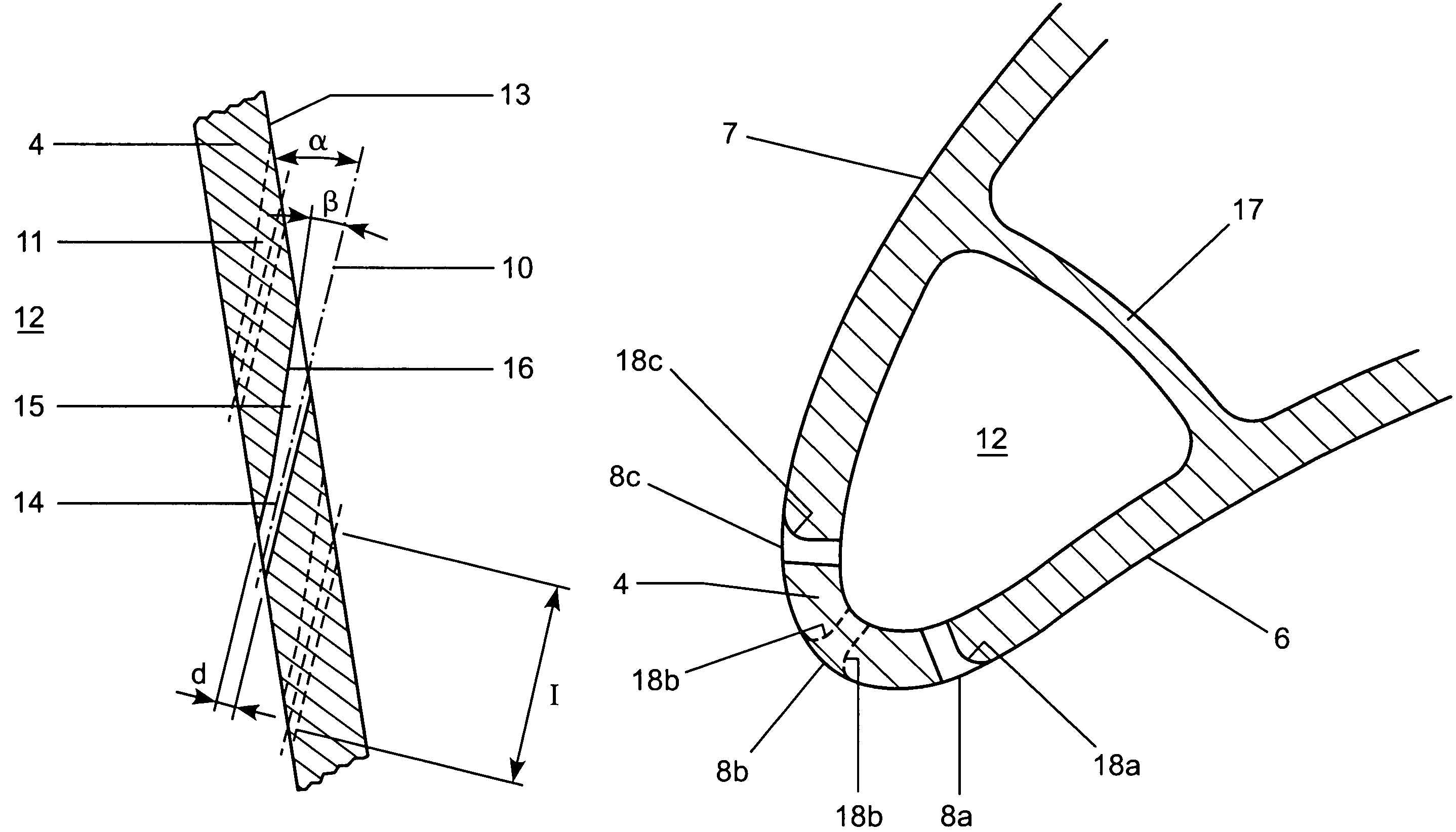
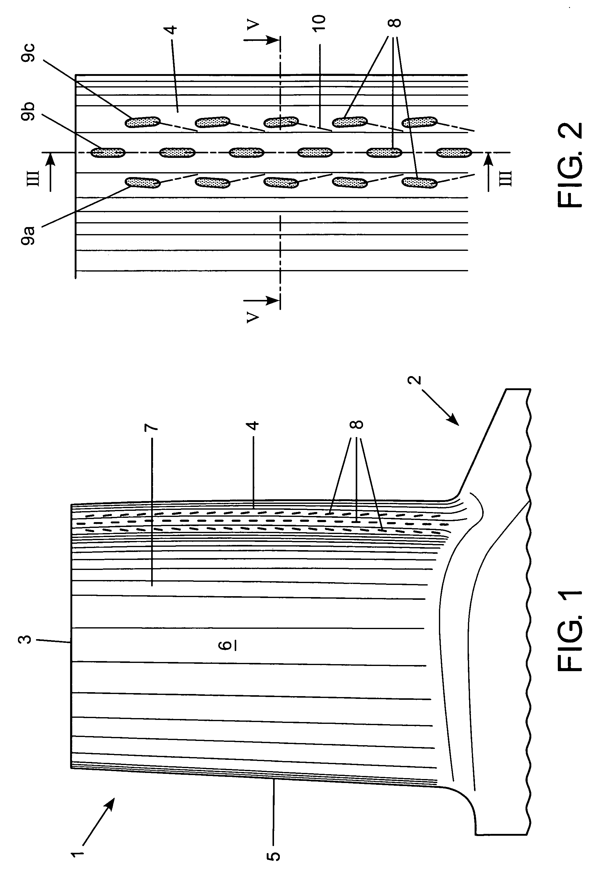
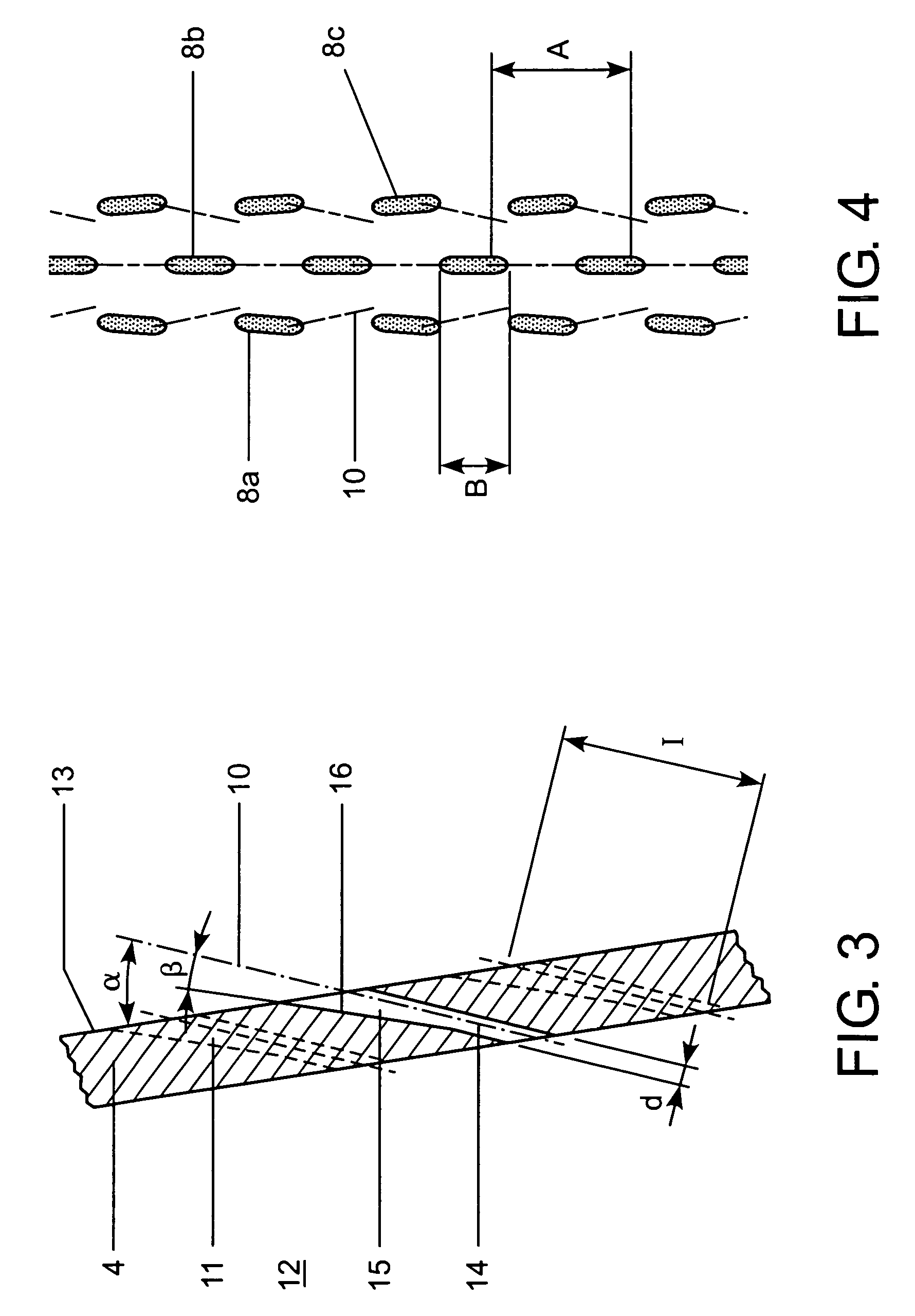
[0028]FIG. 1 shows a gas turbine airfoil 1 extending from a root 2 to a tip 3 and comprising a leading edge 4 and a trailing edge 5. Enclosed by a pressure sidewall 6 and a suction sidewall 7 are several passages for cooling air to pass through that has been bled from a cooling air source such as a compressor. The cooling air passing through these passages convectively cools the gas turbine airfoil, which protects the airfoil metal from overheating. Additional cooling is necessary in the region of the leading edge 4 of the airfoil. It is realized by means of film cooling holes leading from the internal cooling air passages to the outer surface of the airfoil where the cooling air flows along the airfoil surface in the manner of a film. This invention and the figures described here pertain particularly to the leading edge. The airfoil comprises multiple film cooling holes positioned along the leading edge between its root 2 and tip 3. Exit ports 8 of the film cooling holes are arrang...


PUM


Abstract

A gas turbine airfoil with a pressure sidewall (6) and a suction sidewall (7) extends from a root (2) to a tip (3) and from a leading edge (4) to a trailing edge (5). It comprises several film cooling holes with exit ports (8). The film cooling holes have a sidewall that is diffused in the direction of the tip (3) of the airfoil (1) at least over a part of the film cooling hole. Furthermore, the film cooling holes each have flare-like contour near the outer surface of the leading edge (4). The film cooling holes according to the invention provide an improved film cooling effectiveness due to reduced formation of vortices and decreased penetration depth of the cooling air film.

Description

FIELD OF INVENTION[0001]This invention pertains to a gas turbine airfoil and in particular to a cooling construction for its leading edge.BACKGROUND ART[0002]Airfoils of gas turbines, turbine rotor blades and stator vanes, require extensive cooling in order to keep the metal temperature below a certain allowable level and prevent damage due to overheating. Typically such airfoils are designed with hollow spaces and a plurality of passages and cavities for cooling fluid to flow through. The cooling fluid is typically air bled from the compressor having a higher pressure and lower temperature compared to the gas traveling through the turbine. The higher pressure forces the air through the cavities and passages as it transports the heat away from the airfoil walls. The cooling construction further comprises film cooling holes leading from the hollow spaces within the airfoil to the external surfaces of the leading and trailing edge as well as to the suction and pressure sidewalls.[0003...

Claims


Application Information

Patent Timeline
Patent Type & Authority Patents(United States)
IPC IPC(8): F01D5/18
CPCF01D5/186
Inventor LIANG, GEORGE
Owner ANSALDO ENERGIA IP UK LTD
Why Eureka
Try Eureka