Integrated platform, tip, and main body microcircuits for turbine blades

a turbine blade and microcircuit technology, applied in the direction of liquid fuel engines, machines/engines, mechanical equipment, etc., can solve the problems that the objective is extremely difficult to achieve with current cooling technology, and achieve the effect of improving heat pick-up, improving cooling effectiveness and convective efficiency, and improving film cooling

Active Publication Date: 2009-06-30
RTX CORP
View PDF11 Cites 9 Cited by
  • Summary
  • Abstract
  • Description
  • Claims
  • Application Information

AI Technical Summary

Benefits of technology

[0005]To improve the cooling effectiveness and the convective efficiency, several approaches are required. First, coating the airfoil with a thermal barrier coating is a first requirement. The other requirements are: (1) improved film cooling in terms of slots for increased film coverage; (2) improved heat pick-up; and (3) improved heat transfer coefficients in the blade cooling passages. With that in mind, the overall cooling effectiveness will approach 0.8 with a convective efficiency approaching 0.5, allowing for a lower cooling flow of no more than 3.5% of the engine core flow.

Problems solved by technology

That objective is extremely difficult to achieve with current cooling technology which is shown schematically in FIGS. 2 and 3.

Method used


Image

  • Integrated platform, tip, and main body microcircuits for turbine blades
  • Integrated platform, tip, and main body microcircuits for turbine blades
  • Integrated platform, tip, and main body microcircuits for turbine blades

Examples


Embodiment Construction

)

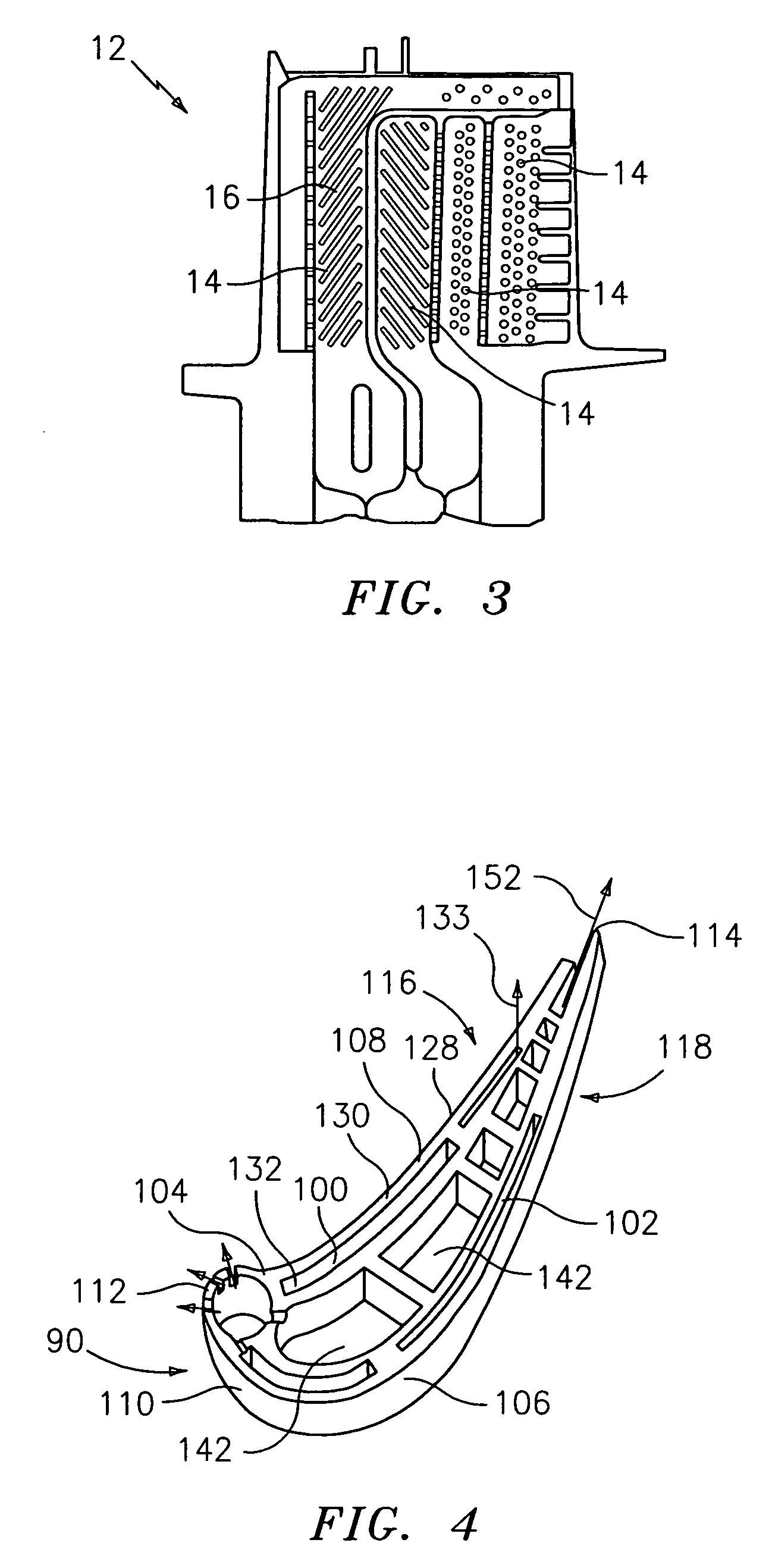
[0018]As noted above, to improve the cooling effectiveness and the convective efficiency, several approaches are required. First, coating the airfoil with a thermal barrier coating is a first requirement. The other requirements are: (1) improved film cooling in terms of slots for increased film coverage; (2) improved heat pick-up; and (3) improved heat transfer coefficients in the blade cooling passages. With that in mind, the overall cooling effectiveness will approach 0.8 with a convective efficiency approaching 0.5, allowing for lower cooling flow of no more than 3.5%. One such design is shown in FIG. 4.

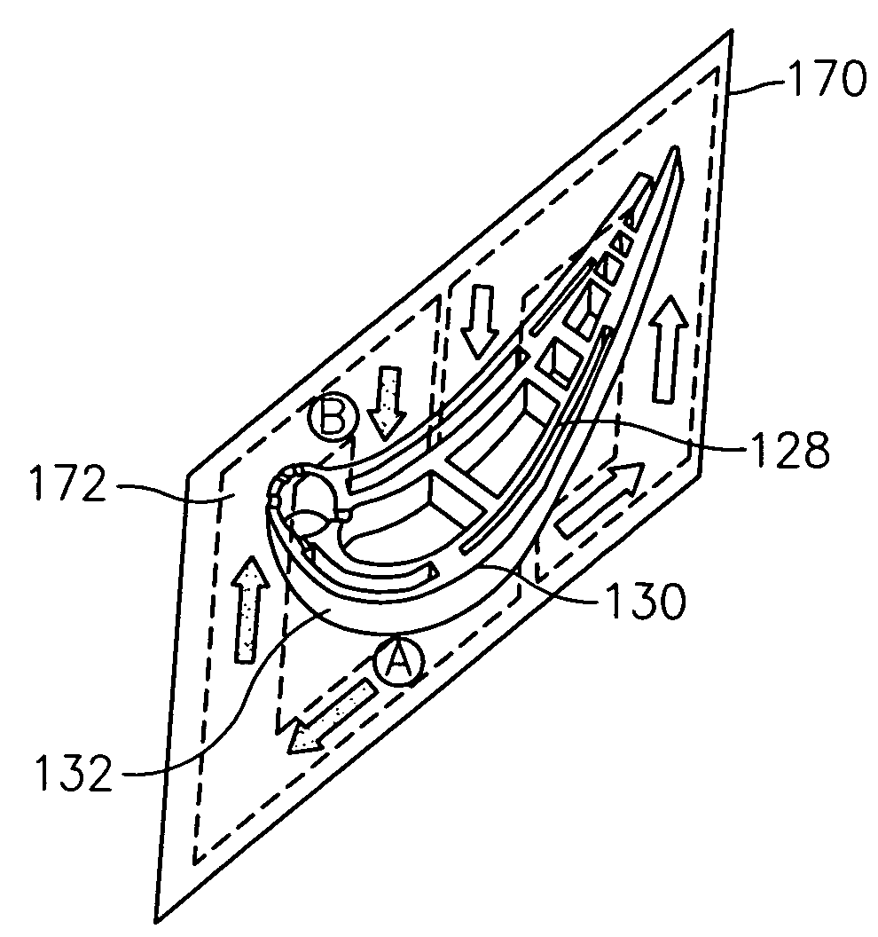
[0019]Referring now to the drawings, a turbine engine component 90, such as a high pressure turbine blade, is cooled using the cooling design scheme of the present invention. The cooling design scheme, as shown in FIG. 4, encompasses two serpentine microcircuits 100 and 102 located peripherally in the airfoil walls 104 and 106 respectively for cooling the main body 108 of the air...


PUM


Abstract

A turbine engine component has an airfoil portion with a pressure side and a suction side. The turbine engine component further has a first cooling microcircuit for cooling the suction side of the airfoil portion. The first cooling microcircuit is embedded within a first wall forming the suction side. The first cooling microcircuit has a circuit for allowing a cooling fluid in the first cooling microcircuit to exit at a tip of the airfoil portion. The turbine engine component also has a second cooling microcircuit embedded within a second wall forming the pressure side of the airfoil portion.

Description

BACKGROUND[0001](1) Field of the Invention[0002]The present invention relates to a turbine engine component having an integrated system for cooling the platform, the tip, and the main body of an airfoil portion of the component.[0003](2) Prior Art[0004]FIG. 1 depicts an engine arrangement 10 illustrating the relative location of a high pressure turbine blade 12. FIGS. 2 and 3 depict the main design characteristics of a typical conventionally cooled high-pressure blade 12. In general, cooling flow passes through these blades by means of internal cooling channels 14 that are turbulated with trip strips 16 for enhancing heat transfer inside the blade. The cooling effectiveness of these blades is around 0.50 with a convective efficiency of around 0.40. It should be noted that cooling effectiveness is a dimensionless ratio of metal temperature ranging from zero to unity as the minimum and maximum values. The convective efficiency is also a dimensionless ratio and denotes the ability for ...

Claims


Application Information

Patent Timeline
Patent Type & Authority Patents(United States)
IPC IPC(8): F01D5/18
CPCF01D5/186F01D5/188
Inventor CUNHA, FRANCISCO J.ABDEL-MESSEH, WILLIAM
Owner RTX CORP
Why Eureka
Try Eureka