
Armature, wire dot printer head and wire dot printer
a printer head and wire dot technology, applied in the field of wire dot printers, can solve the problems of insufficient joining force, unable to obtain sufficient joining force, and difficulty in reducing a dimensional tolerance at the engagement section, and achieve the effect of durability of the armatur
- Summary
- Abstract
- Description
- Claims
- Application Information
AI Technical Summary
Benefits of technology
Problems solved by technology
Method used
Image

Examples
Embodiment Construction
[0023]Preferred embodiments for carrying out the present invention will be explained with reference to FIGS. 1 to 6.
[0024][Wire Dot Printer Head]
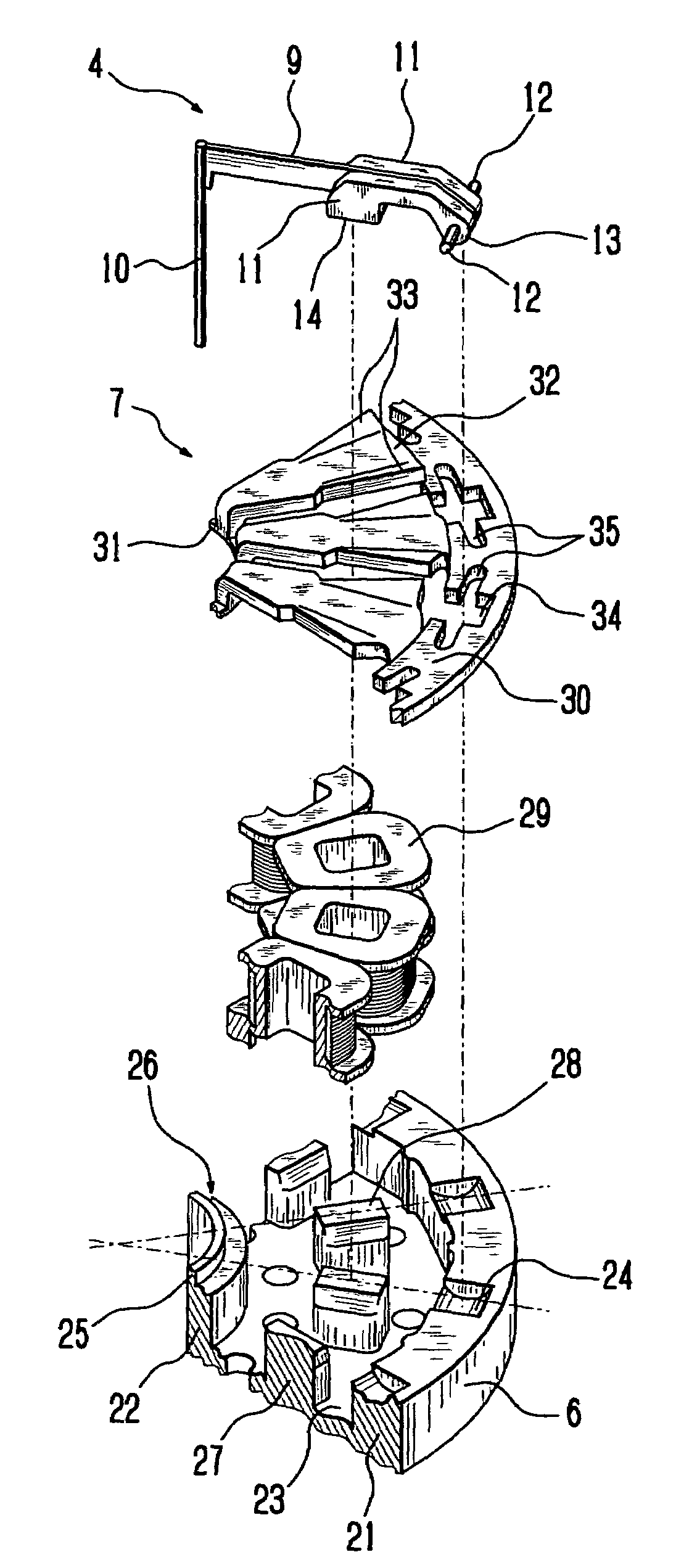
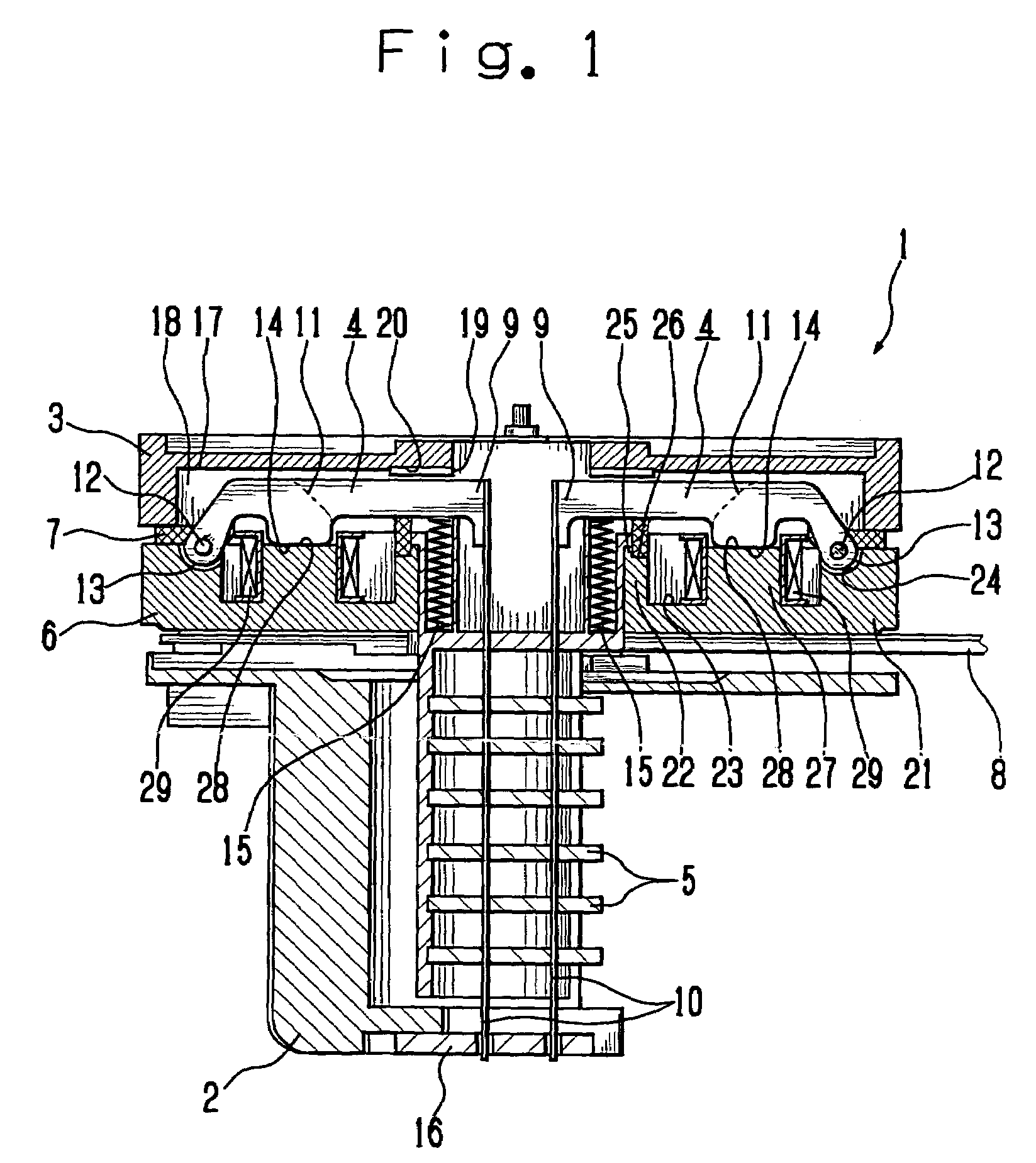
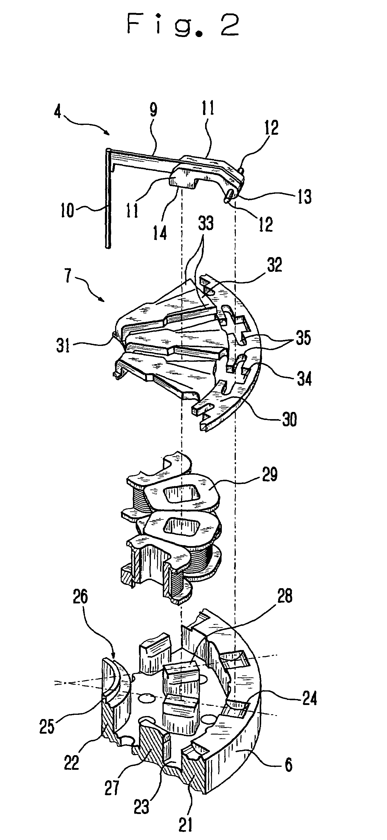
[0025]Firstly, the entire construction of a wire dot printer head 1 will be explained with reference to FIGS. 1 to 4. FIG. 1 is a front view in central vertical section schematically showing a wire dot printer head 1 according to the embodiment and FIG. 2 is an exploded perspective view schematically showing a part of the wire dot printer head 1.
[0026]The wire dot printer head 1 has a front case 2 and a rear case 3 coupled together with a mounting screw (not shown). Disposed between the front case 2 and the rear case 3 are armatures 4, wire guides 5, yoke 6, armature spacer 7, and circuit board 8.
[0027]Each of the armatures 4 has an arm 9 that is formed into a plate-like shape and supports a printing wire (hereinafter simply referred to as a wire) 10 at one end thereof in the lengthwise direction (in the direction in which the arm 9 extends...
PUM
 Abstract
Description
Claims
Application Information