High-efficiency solar-charging LED window candle

a solar-powered, window candle technology, applied in the direction of lighting, heating apparatus, instruments, etc., can solve the problems of no existing battery, inability to achieve, and large amount of power to light incandescent window candles, so as to reduce the current requirements of led without sacrificing brightness or aesthetics, and improve light collection

Inactive Publication Date: 2008-04-22
TROMBETTA VINCE +1
View PDF9 Cites 21 Cited by
  • Summary
  • Abstract
  • Description
  • Claims
  • Application Information

AI Technical Summary

Benefits of technology

[0014]It is still another object to provide dual (front and back) inclined solar cells for more efficient charging, and a photosensing circuit that employs the existing solar cells to sense ambient light, for automatically turning the power to the LED off during the day and on at night, effectively allowing the device to charge all day and illuminate all night.
[0015]It is still another object to power the white LED by a charge pump circuit for reducing the current requirements of the LED without sacrificing brightness or aesthetics.
[0016]These and other objects are accomplished with the improved high-efficiency solar-charging LED window candle of the present invention, which generally comprises a narrow base adapted to sit securely upon a window sill, the base being formed with a battery compartment accessible through a bottom hatch, and a riser section protruding upwardly with inclined side surfaces, the riser also being formed with a compartment for enclosing circuitry, and a vertically-oriented collar for receiving a candle body. Dual (front and back) solar cells are mounted on the inclined surfaces of the riser for recharging the battery during the day from solar light, and at night from inside lighting. This configuration yields an aesthetically pleasing appearance, plus the solar cells are mounted along a steep incline for better light collection. The candle body comprises a cylindrical length of white plastic compression-fit into the collar and extending upward approximately one foot to a screw-in bulb receptacle (in this case the receptacle is not wired). A light bulb assembly is screwed into the bulb receptacle, the light bulb assembly comprising a glass light-bulb housing enclosing a white LED with shielded leads. The glass light-bulb housing is essentially an incandescent candle light bulb with glass candle-shaped bulb secured to a screw-threaded male base, but the base is tapped to remove the filament. Instead, the leads of the white LED are connected upward through the tapped base and the LED is mounted where the filament normally sits. The LED is connected to a circuit board residing in the riser of the base. A photosensing circuit resides on one circuit board, and this measures the current output from the two solar cells to sense ambient light, for automatically turning the power to the LED off during the day and on at night, effectively allowing the device to charge all day and illuminate all night. The circuit board also contains a charge pump circuit for reducing the current requirements of the LED without sacrificing brightness or aesthetics. This allows illumination of a white LED (characteristically high current drain) for an astounding 24-48 hours between charges.
[0017]The present invention's design is simple and straightforward, and can be economically manufactured.

Problems solved by technology

Unfortunately, flame candles pose a fire hazard.
Still, it takes a large amount of power to light an incandescent window candle all night, and no existing battery can achieve this.
However, even with a full charge the candle burns only 4-5 hours.

Method used


Image

  • High-efficiency solar-charging LED window candle
  • High-efficiency solar-charging LED window candle
  • High-efficiency solar-charging LED window candle

Examples


Embodiment Construction

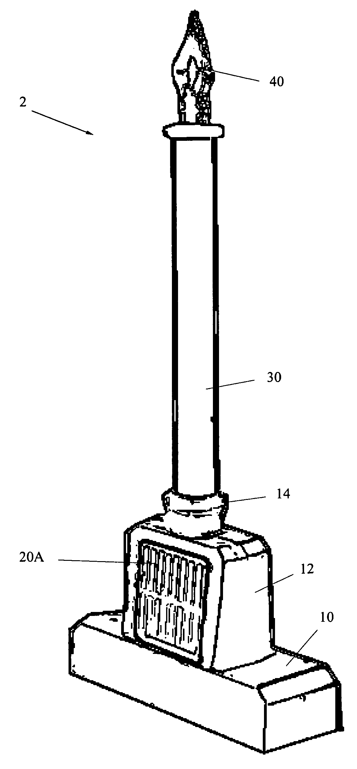
[0026]The present invention is an improved high-efficiency solar-charging LED window candle that is battery powered and solar-charging. The electric candle charges during the day and automatically illuminates after dark.

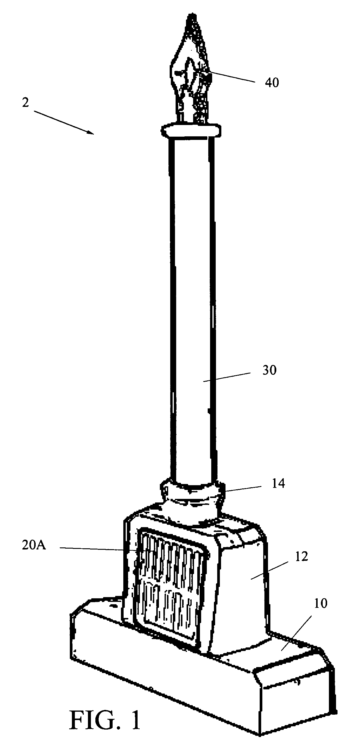
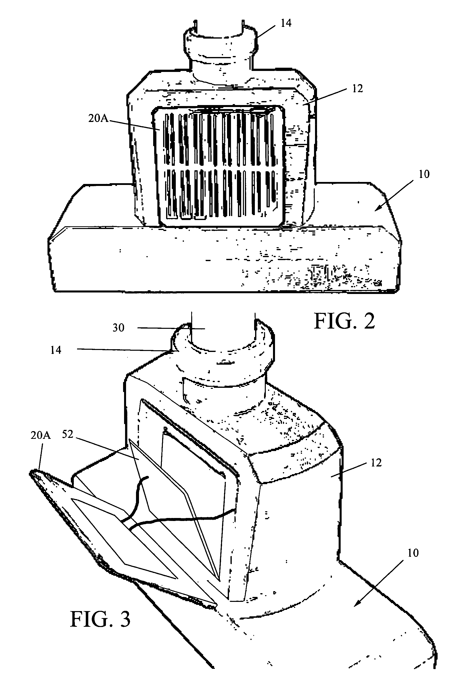
[0027]Referring to FIG. 1 a preferred embodiment of electric candle light 2 is shown. The electric candle light 2 has a decorative base 10 formed of wood or the like. The base 10 is approximately 5″ long and 2″ wide so that it can fit on a standard window sill of a house window. Base 10 is hollow and accessible through a removable panel in the bottom for insertion of a NiCad battery pack. A riser 12 extends upwardly from the base 10, the riser 12 being formed substantially hollow with a central enclosure (obscured) for seating the circuit board of the present invention. The riser 12 is also formed with inclined recesses in the front and rear for mounting opposing solar cells at an angle, and a vertically-oriented collar 14 at the top for receiving a candle body 30. T...


PUM


Abstract

Disclosed herein is an improved high-efficiency solar-charging electric window candle comprising a base adapted to sit securely upon a window sill. The base includes a footer formed with a battery compartment accessible through a bottom hatch, and a riser protruding upwardly from the footer with upwardly inclined side surfaces. The riser also has a compartment for enclosing a circuit board, and a vertically-oriented collar. A rechargeable battery is mounted in the footer of said base, and a hollow cylindrical candle body is inserted in the collar of the base riser, and a bulb assembly comprising a white LED is mounted atop the candle body. A circuit board is enclosed in the riser and includes two circuits: a current pump for supplying a pulsed current, and a photosensing circuit for sensing ambient light levels. The charge pump circuit reduces current requirements of the white LED, and the photosensing circuit automatically detects ambient light levels and illuminates the white LED while disconnecting the rechargeable battery, or vice versa, depending on whether there is sufficient ambient light.

Description

CROSS-REFERENCE TO RELATED APPLICATION(S)[0001]The present application derives priority from U.S. provisional application no. 60 / 656,452 filed Feb. 28, 2005.BACKGROUND OF THE INVENTION[0002]1. Field of the Invention[0003]The present invention relates to decorative candle lighting systems and, more particularly, to a battery-powered solar-recharging electric candle lighting system for use in a window sill.[0004]2. Description of the Background[0005]There has long been a widespread Christmas tradition of placing candles in windows. Many believe that this tradition dates back to early Christianity. The custom exists in several European countries including France, England, Ireland and Denmark.[0006]The first of the 13 original colonies, Virginia, takes credit for adopting the tradition in the USA. In colonial Virginia a candle in the window was a gesture of welcome and a promise of warm hospitality to guests. While the meaning may have faded, the candle in the window is still a widespre...

Claims


Application Information

Patent Timeline
Patent Type & Authority Patents(United States)
IPC IPC(8): F21L19/00
CPCF21S6/001H05B33/0803H05B33/0809F21W2121/00Y10S362/806Y10S362/81H05B45/37H05B45/3574H05B45/345H05B45/12
Inventor TROMBETTA, VINCETRUMP, KEVIN
Owner TROMBETTA VINCE
Why Eureka
Try Eureka